Eurocode 7 Design Example
- Oct 25, 2023
- 4 min read
Updated: Apr 29
Eurocode 7 design example for a simple braced excavation
In order to better illustrate how EC7 procedures are applied, a simple example solved with traditional limit equilibrium methods is first presented (Figure 1).
This imaginary example comprises a 9m deep excavation, supported by an 18m long wall, braced by one ground anchor located at 3m below the wall top and inclined at 30 degrees from the horizontal.
Retained ground water is located at 5m depth while water inside the excavation is maintained at subgrade.
For reasons of simplicity the analyses assume one soil type, Rankine active earth pressures on the retained side, and Rankine passive earth pressures on the excavated side.
A simplified one-dimensional water flow is considered for all construction stages and the wall is analyzed with the free earth method.
The excavation was analyzed for the service case (SLS), for a typical US approach with a typical 1.5 safety factor on the SLS results, and last for all EC7 ULS combinations (DA-1, DA-2, DA-3).
Table 4 compares critical results computed with the aforementioned design scenarios.
It is emphasized that this example does not represent an optimized design.
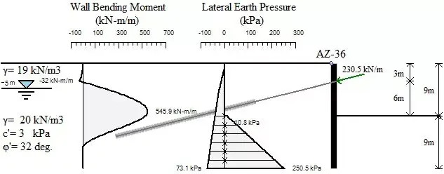
Figure 1. Example of typical braced excavation (with service analysis results)
Table 4. Comparison combination methods for braced excavation example with traditional limit equilibrium approach.
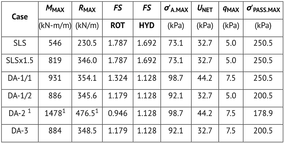
Notes: 1. Case DA-2 model does not converge
σ'A.MAX = Maximum computed unfavorable active earth pressure (including partial factors)
σ 'PASS.MAX = Maximum computed passive earth resistance pressure (including partial factors)
FS ROT = Wall embedment safety factor against rotation (free earth method)
FS HYD = Hydraulic heave safety factor
MMAX = Maximum computed wall bending moment
RMAX = Maximum computed support reaction at the anchorage direction
UNET = Maximum computed unfavorable net water pressure (including partial factors)
qMAX = Maximum computed unfavorable variable load (including effects of partial factors)
In this example, all EC7 combinations produced greater ultimate wall moments and support reactions when compared with the typical US approach (with a safety factor of 1.5).
It is worth to note that EC7 combination DA-2 failed to converge as the earth resistance was not sufficient to fix the wall.
While all methods that converged resulted in a similar ultimate anchor reaction, ultimate wall bending computed with EC7 combinations was from 8% to 13.5% greater compared to the SLS x 1.5 approach (where service analysis results are multiplied times 1.5).
This difference is equivalent to applying a safety factor of 1.6 to 1.7 on the SLS wall bending results.
Next, the same example is examined with a well established nonlinear beam-on-elastoplastic foundation solution (DeepEX 2010, Nova et. al. 1987).
In this approach, the soil is modeled as a series of stage-dependent nonlinear soil springs on both the retained and the excavated sides.
In addition to the limit-equilibrium method, nonlinear soil-structure interaction methods require the definition of the ground anchor prestress, the elastic soil and support properties, and equally important determination of the initial lateral earth pressures (i.e. at-rest lateral earth pressure coefficients).
Table 5 compares critical results for the excavation of figure 1 computed with the nonlinear solution for the same design scenarios.
Table 5. Comparison of different combination methods for braced excavation example with beam-on-elastoplastic foundations approach.
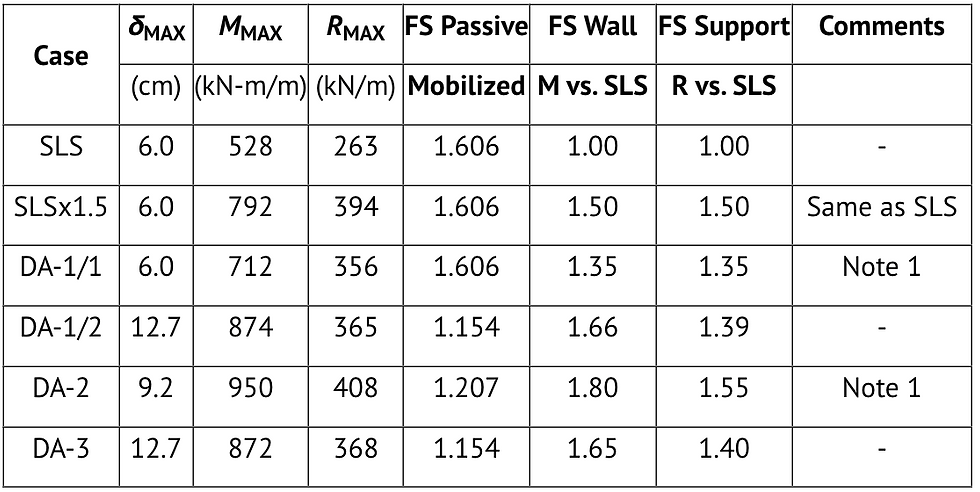
Note: 1. Combination performed by standardizing analysis by γG = 1.35
δMAX = Maximum horizontal wall displacement
Table 5 reveals many interesting points for discussion.
First, combinations DA-1/1 and DA-2 are standardized by the partial safety factor for unfavorable permanent actions (1.35).
In this procedure, initially all variable load actions are divided by γG, passive coefficients are adjusted for the (R) set of partial safety factors, and an equivalent service analysis is performed.
The final results are then obtained by multiplying the standardized SLS analysis results by γG.
This standardization is the only available analysis option when water levels differ between the retained and excavated sides (multiplication of water pressures by a safety factor in a nonlinear solution is virtually impossible and theoretically inconsistent since vertical effective stress and water pressures are coupled).
In this example, the EC7 design approach combinations result in wall bending moments that differ by -10% to 20% of the SLS x 1.5 case maximum wall bending (with corresponding safety factors ranging from 1.35 up to 1.80).
EC7 results for the anchor reaction exhibit a smaller scatter compared to the wall bending around the SLS x 1.5 analysis scenario (from 90% to 103%, or overall safety factors from 1.35 to 1.55).
In the nonlinear solution, the standardization procedure essentially allows the DA-2 combination to be computed, whereas, the analysis could not converge for the limit-equilibrium approach.
In a nonlinear analysis the passive mobilization safety factor can be particularly valuable in assessing excavation performance
Given that in a ULS approach a FS≥ 1.0 is desired, one would immediately tend to render the safety factor FS= 1.2 in case DA-2 as acceptable.
This apparent discrepancy can be misleading since the combination was analyzed with a standardized SLS approach.
It can thus be argued, that in this case the minimum safety factor equal to the standardization factor is desirable (i.e. FSPassive.Mobilized ≥ 1.35).
This example was analyzed with our DeepEX software (Earth Retention conference 2010).
DeepEX Software implements several Structural and Geotechnical Design Codes
AASHTO LRFD, CALTRANS, EUROCODES 2, 3, 7, 8, ACI, BS, Australian Codes, Chinese Codes +more!
Solutions for Geotechnical Engineering Professionals:

DeepEX: Deep Excavations Design Software

DeepFND: Pile Foundations Design Software

HelixPile Helical Piles Design Software