

Secant Pile Wall - Circular Shaft Design Example
- Dec 26, 2023
- 3 min read
Updated: Apr 28
Circular Shaft - Secant Piles - 20ft Excavation
In this example we will design a secant piles circular shaft, supporting a 20ft excavation. The model is created and analyzed with DeepEX - Shoring Design Software.
A. Project Description
In this example we will design secant pile wall circular shaft, supporting a 20ft excavation. The Figure below presents the project model. Tables 1 and 2 present the soil properties and the stratigraphy respectively. Table 3 presents the external loads. Tables 4 and 5 present the wall and support properties respectively. The general ground surface is at El. 0ft and the general water table is at El. -50 ft.

Figure: Project model.
Table 1: Soil properties.
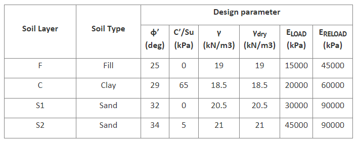
Table 2: Stratigraphy.

Table 3: External loads.

Table 4: Wall parameters.

Table 5: Support parameters.

B. Modeling with DeepEX
The model will be created using the DeepEX Model Wizard:
Define Analysis Methods:

Figure: Analysis Methods in DeepEX Wizard.
In this dialog, we choose to apply the combination method to our model (Limit Equilibrium and Non-Linear). For the classical earth pressures in design stages with multiple support levels we define FHWA apparent pressures and for the beam analysis we choose CALTRANS method. The combination method will first run the Limit Equilibrium Analysis and calculate the wall embedment FS, and then will run the Non-Linear Analysis and present these results on the tables and on the model area graphically.
Define project type and dimensions

Figure: Project Type and Dimensions in DeepEX Wizard.
In this dialog we select the project type (in this case we select the option to create a circular shaft model). Next, we define the project dimensions (final excavation depth, walls depth, excavation width, top of the wall elevation and water table).
Define soil types and stratigraphy

Figure: Soil Properties and Soil Layers in DeepEX Wizard.

Figure: Soil Properties and Soil Layers dialogs in DeepEX.
In these dialogs we can define the required soil types and the properties for each created soil, as well as, the model stratigraphy by defining the top of the soil layer elevation and the soil type in each layer.
Define wall type and wall section properties

Figure: Wall types in DeepEX Wizard.

Figure: Wall Sections dialog in DeepEX.
In these dialogs we select the wall section type (in this case secant pile wall), the steel pile section, the wall spacing and the concrete – steel materials.
Supports

In this dialog, we define the dimensions of the supports we wish to use in the model. We will use a cap beam and a ring beam at EL: -10 ft. We check the support types and we define the support dimensions.
Define Stages – Support Elevations

Figure: Support Elevations in DeepEX Wizard.
In this dialog, we define the depth from the surface or each support level, as well as, the depth below each support level where we wish to excavate in the stages, before the support is installed. The software automatically calculates all elevations (excavations and support installation levels) of these defined depths and generates all intermediate construction stages.
Define Surcharge

Figure: Support Elevations in DeepEX Wizard.
In this dialog we define the surcharge type and properties, as well as the surcharge modeling options. In this case we will use a 0.6 kips strip surcharge, developed for 50 ft, starting 1ft behind the left wall. After the model is automatically generated by the software wizard, we can access the stages in the model area and add any required additional loads graphically, using the Draw Loads options in the General tab of DeepEX.
Define structural codes:

Figure: Structural Codes in DeepEX Wizard.
In this dialog, we can define the structural and geotechnical design codes that we wish to assign to this model. In this case, we will use US allowable settings for steel design and ACI for concrete.
The software automatically creates all project construction stages, according to our selections in the Model Wizard. The following Figures present the models in Stage 3:

Figure: Generated Model – Stage 3.
C. Circular Shaft Analysis and Results
Since the model is ready, we can choose to calculate the design section, pressing on the button

After the analysis is succeeded, the Summary table appears. The table below includes some critical checks and values for each construction stage. The last columns of the Analysis and Checking summary Table, present the Circular Shaft results (Hoop Buckling Safety actor, Hoop Force etc). The following figures present some graphical results from the results tab of DeepEX.
Table: DeepEX critical results/stage

Table: DeepEX critical results/stage - Hoop Results


Figure: Wall moment and hoop force diagrams, Stage 3.

Figure: Wall deflections and soil pressures diagrams, Stage 3.


