Cut-and-Cover Tunnel Design and Analysis
- Feb 13, 2024
- 7 min read
Top-Down VS Bottom-Up Construction Methods, 2D FEM & 3D FEM Analysis
A. INTRODUCTION
This article delves into two primary methodologies employed in the construction of cut-and-cover tunnels – the top-down and bottom-up approaches. Each method entails distinct steps, brings its own set of advantages, and is constrained by specific limitations, all of which will be explored comprehensively in the subsequent sections. While the ultimate visual outcome of the project may appear similar, the intricacies of the construction stages introduce variations in internal forces and displacements. These subtle differences can be observed through the lens of finite element analysis, leveraging simulations that meticulously consider every intermediate step.
Within the scope of this exploration, we will provide a comparative analysis using DeepEX – a shoring design software. Through detailed simulation and consideration of all construction phases, we aim to showcase the finite element analysis results, allowing for a nuanced comparison of critical stresses and displacements generated by both the top-down and bottom-up approaches. Our examination is not merely theoretical; it extends to practical application with the inclusion of examples that vividly illustrate the significance of each construction method.
To further enhance understanding, we present a 3D Finite Element analysis model for a cut-and-cover tunnel constructed using the bottom-up excavation method. This model is accompanied by a detailed presentation of the 3D finite element analysis results, offering insights into the intricate dynamics of the construction process. Additionally, shadings are employed to visually communicate key findings, providing a comprehensive overview of the structural implications associated with the top-down construction approach.

Figure: A cut-and-cover tunnel simulated in DeepEX software
B. TOP-DOWN VS BOTTOM-UP CONSTRUCTION METHODS
Cut-and-cover tunnels and excavations are common construction methods used for creating underground structures like tunnels or subway stations. The top-down and bottom-up approaches are two main methods employed in this construction process.
Top-Down Approach:
In the top-down approach, construction begins by excavating a large open trench at ground level. Once the trench is dug, a support structure is built to protect the sides and prevent collapse. The construction then proceeds downward in layers. As the excavation deepens, the tunnel structure is built incrementally. The surface is gradually restored as construction proceeds deeper into the ground.
Steps:
- Excavation: Dig a large trench at ground level.
- Support Structure: Construct a support structure to prevent collapse.
- Layered Construction: Build the tunnel structure incrementally as excavation progresses.
- Surface Restoration: Gradually restore the surface as construction moves deeper.
Advantages:
- Early Accessibility: Allows for early access to the tunnel's lower levels for construction and installation.
- Minimized Disruption: Surface disruption is reduced as construction proceeds underground.
Limitations:
- Space Requirement: Requires significant open space for the initial excavation.
- Surface Disruption during Construction: Disruption is still experienced at the beginning of the construction process.
Bottom-Up Approach:
In the bottom-up approach, construction starts by digging a small pilot tunnel or shaft at the tunnel's final depth. The tunnel is then constructed upwards and gradually expanded. The surface is disrupted only during the initial shaft construction.
Steps:
- Pilot Tunnel/Shaft: Excavate a small pilot tunnel or shaft at the final depth.
- Construction Upwards: Build the tunnel structure upwards and expand as needed.
- Surface Disruption: Limited disruption at the surface mainly during the initial shaft construction.
Advantages:
- Reduced Surface Disruption: Disruption is confined to the initial shaft construction phase.
- Suitable for Urban Areas: Well-suited for construction in densely populated urban areas.
Limitations:
- Late Accessibility: Lower levels of the tunnel are accessible later in the construction process.
- Complex Construction Logistics: Coordination is required for material and equipment to be lowered into the construction site.
Both approaches have their unique advantages and limitations, and the choice between them depends on factors such as site conditions, available space, and the specific requirements of the project. The decision often involves a careful evaluation of the trade-offs between early accessibility, surface disruption, and overall construction efficiency.
C. COMPARISON EXAMPLE – PROJECT PROPERTIES & SOFTWARE MODELS
In the upcoming sections, we'll showcase simulations of a 9-meter deep excavation for a cut-and-cover tunnel. This tunnel features 1-meter thick reinforced concrete walls, a base slab, and a top slab. These simulations were meticulously designed using the DeepEX software, covering all intermediate construction stages for each of the mentioned methods. Table 1 presents the soil properties and stratigraphy used in this example.
Table 1: Assumed soil properties and stratigraphy
Soil | Top El. | Description | Unit Weight | Friction Angle | C’ | Soil Behavior | Eload | exp |
(-) | (m) | (-) | (KN/m3) | (deg) | (kPa) | (-) | (kPa) | (-) |
F | 0 | Fill - Sand | 19 | 32 | 2 | Exponential | 20000 | 0.45 |
S1 | -3 | Medium Dense Sand | 21 | 34 | 4 | Exponential | 28000 | 0.4 |

Figure: Soil properties and soil layer options in DeepEX software
Case 1: Top-Down excavation model
In the first scenario we will simulate the following construction stages in DeepEX software:
- Stage 0: Wall installation (1 meter thick reinforced concrete diaphragm walls, 12 meters deep).
- Stage 1: Initial excavation to elevation -1m
- Stage 2: Installation of the top slab at elevation -0.5m (1 meter thick concrete slab)
- Stage 3: Excavation to elevation -5m
- Stage 4: Installation of intermediate strut row (PM600x19 steel struts at 6 meters horizontal spacing)
- Stage 5: Excavation to elevation -9m
- Stage 6: Installation of the base slab at elevation -8.5m (1 meter thick concrete slab)
- Stage 7: Removal of the intermediate strut row

Figure: Cut and cover tunnel model – Top-Down excavation stages in DeepEX
Case 2: Bottom-Up excavation model
In the second scenario we will simulate the following construction stages in DeepEX software:
- Stage 0: Wall installation (1 meter thick reinforced concrete diaphragm walls, 12 meters deep).
- Stage 1: Initial excavation to elevation -3m
- Stage 2: Installation of the first strut row (PM600x19 steel struts at 6 meters horizontal spacing)
- Stage 3: Excavation to elevation -6m
- Stage 4: Installation of second strut row (PM600x19 steel struts at 6 meters horizontal spacing)
- Stage 5: Excavation to elevation -9m
- Stage 6: Installation of the top and base slabs (1 meter thick concrete slabs at El: -0.5m and El: -8.5m)
- Stage 7: Removal of the intermediate strut rows

Figure: Cut and cover tunnel model – Bottom-Up excavation stages in DeepEX
D. COMPARISON EXAMPLE – ANALYSIS SETTINGS AND 2D FEM ANALYSIS RESULTS
We will analyze the generated models with the DeepEX 2D FEM analysis engine, considering 80% of the soil friction angle as wall friction and selecting a medium dense mesh during the analysis. The following images illustrate the calculated soil displacement shadings, the wall moment diagrams and the structural check rations for the supports in different construction stages (Stages 1, 4, 6 and 7 respectively).

Figure: DeepEX 2D FEM results for each examined scenario – Stage 1
In this stage, a notable observation is that the greater excavation depth in the bottom-up construction method leads to the generation of larger moments on the retaining walls. The increased depth plays a significant role in influencing the structural forces, resulting in higher moments compared to other construction methods. This emphasizes the importance of carefully considering excavation depth and its implications on the structural integrity and stability of the retaining walls during the construction planning and analysis phases.

Figure: DeepEX 2D FEM results for each examined scenario – Stage 4
In this stage, a noteworthy observation is that the positioning of the two struts in the bottom-up model facilitates the generation of smaller moments on the walls compared to the top-down excavation case. This difference is attributed to the fact that, in the bottom-up approach, the struts are strategically located, influencing the distribution of forces and resulting in reduced moments on the walls. In contrast, the top-down excavation involves placing the top slab at a higher elevation, affecting the moment dynamics on the walls differently.

Figure: DeepEX 2D FEM results for each examined scenario – Stage 6
In this stage, a notable observation is the impact of having four bracing levels in the bottom-up model (comprising two slabs and two strut rows). This configuration results in the development of smaller moments on the walls, altering the shape of the moment diagram compared to the top-down model. In contrast, the top-down model relies solely on support from the top and base slabs along with a middle strut row.
However, it's crucial to consider that the installation of two strut rows in the bottom-up approach may lead to increased estimated project costs and a longer total construction duration. This trade-off between structural efficiency and construction economics underscores the need for a comprehensive evaluation of project priorities and constraints when selecting the optimal construction method.

Figure: DeepEX 2D FEM results for each examined scenario – Stage 7
In the final construction stage, post the removal of intermediate struts, a notable observation emerges: the top-down excavation approach yields higher final moments on the excavation walls compared to the bottom-up method. This discrepancy arises due to the cumulatively higher moments applied to the excavation system throughout the earlier construction stages, a phenomenon effectively captured by the finite element analysis method.
The following table summarizes the most critical results from all construction stages obtained by each examined approach:
Method | Max. Wall Moment (KN-m/m) | Max. Displacement (cm) | Max. Strut Reaction (KN/m) |
Top-Down Method | 372.63 | 1.18 | 446.13 |
Bottom-Up Method | 263.65 | 1.07 | 366.93 |
E. 3D FINITE ELEMENT ANALYSIS MODEL AND RESULTS
With the DeepEX 3D version and the optional 3D FEM module, we revolutionize the process of generating, analyzing, designing, and optimizing any 3D excavation model within minutes. Our cutting-edge technology enables the swift creation of 3D models through user-friendly dialogs, covering all construction stages. Users can effortlessly access and edit support locations and structural sections graphically.
This software not only conducts analyses using various methods, including the 3D FEM approach, but it also performs structural checks on defined supports and walers. Additionally, it offers features such as automatic optimization of support sections, checks on steel connections, and more. The accompanying images visually showcase the generated 3D FEM model, the FEM mesh, and analysis results, including shadings for the soil, walls, and supports.

Figure: Cut-and-cover tunnel with the bottom-up method (Stage 5) – Generated 3D FEM model in DeepEX

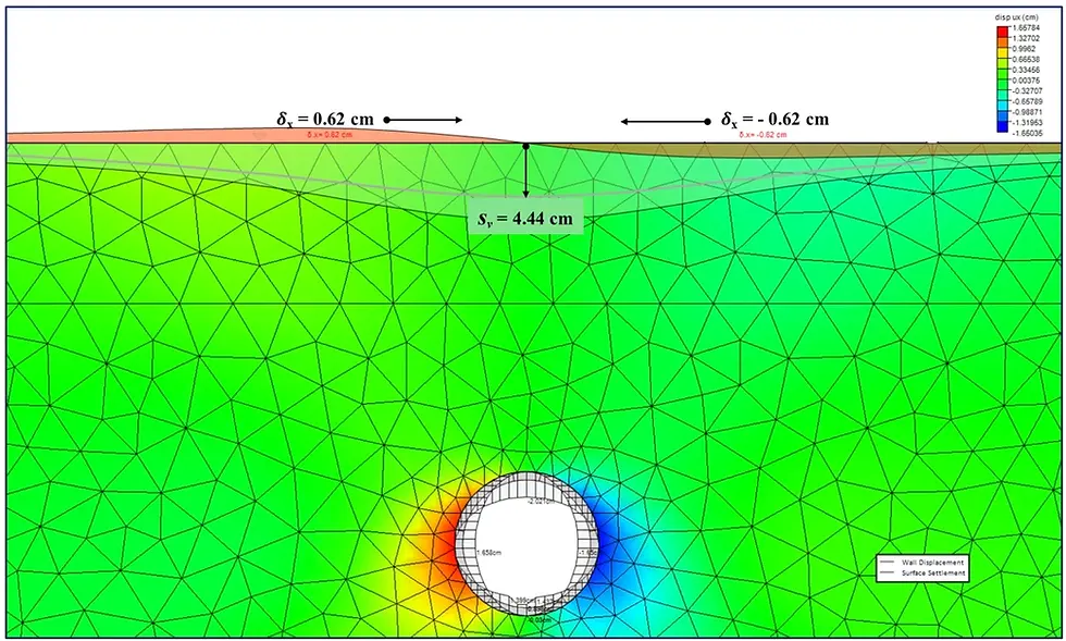
Figure: Cut-and-cover tunnel – DeepEX 3D FEM – Soil settlements (Stage 6)

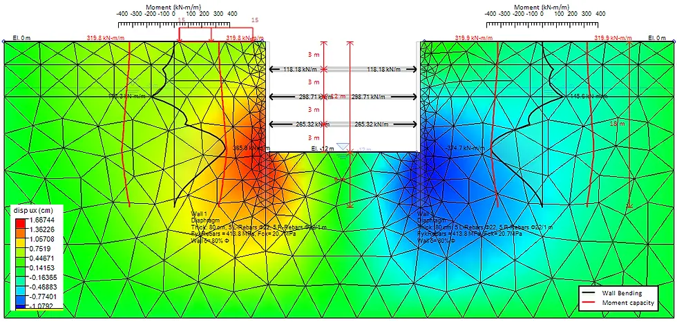
Figure: Cut-and-cover tunnel – DeepEX 3D FEM – Wall moment distribution and strut axial forces (Stage 5)
F. CONCLUSION
A comprehensive understanding of diverse construction methods for geotechnical design engineers and contractors is paramount for successful deep excavation projects. The significance lies not only in recognizing the distinct steps, advantages, and limitations of approaches like top-down and bottom-up but also in the meticulous evaluation of these methods for optimal project design. DeepEX software, with its advanced capabilities, emerges as an indispensable tool. It enables quick and efficient evaluation of various construction scenarios, facilitating informed decision-making.
As we navigate the complexities of deep excavation projects, we encourage geotechnical professionals to explore the prowess of DeepEX, recognizing it as a superior resource for seamless analyses and design optimizations. Test the software, experience its capabilities, and empower your projects with the assurance of cutting-edge technology.