
Analysis, Design and Optimization of an Anchored Soldier Pile Wall with DeepEX
Engineering Example: Comparison of Driven and Drilled Soldier Piles
1. Introduction – The Engineering Challenge
The design of a deep excavation support system requires the evaluation of several interacting parameters, including soil conditions, excavation geometry, wall stiffness, support locations, anchor capacities, and wall embedment. While the primary objective is to develop a safe and reliable support system, engineers must also consider the efficiency of the proposed design and identify opportunities to reduce unnecessary material quantities and construction costs.
Soldier pile walls with tiebacks are commonly used to support deep excavations, particularly when the available space is limited and temporary or permanent earth retention is required. Depending on the ground conditions and construction requirements, steel soldier piles can be driven directly into the ground or installed inside predrilled holes, which are subsequently filled with grout or lean concrete. Although the same steel sections may be used in both cases, the different installation configurations can influence the soil resistance mobilized around the piles and, consequently, the calculated wall embedment requirements.
In this engineering example, we use DeepEX software to analyze, design, and optimize a 9-meter-deep excavation supported by an anchored soldier pile wall. Two alternatives are examined: driven HE320A steel soldier piles and the same steel sections installed in 0.5-meter-diameter drilled and grouted holes. The purpose is to evaluate the behavior of each system, identify potential design improvements, and determine how the installation method affects the optimized wall embedment.
The example follows a practical engineering workflow, starting from an initial wall configuration, reviewing the analysis results, identifying the critical design requirements, and applying optimization procedures. The final objective is not simply to determine which wall can be shorter, but to demonstrate how alternative solutions can be evaluated systematically before selecting the most suitable design.
2. Problem Description and Initial Wall Configuration
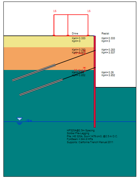
The examined project consists of a 9-meter-deep excavation supported by a soldier pile wall with two levels of tieback anchors. The soldier piles are spaced at 2.5 meters, and 5 cm timber lagging is assumed between the steel sections. The initial wall height is 16 meters, corresponding to a 7-meter embedment below the final excavation level. This preliminary configuration provides the starting point for the analysis and subsequent optimization.
For the first alternative, HE320A steel beams are assumed to be driven directly into the ground. For the second alternative, the same HE320A sections are installed inside 0.5-meter-diameter drilled holes, with the holes subsequently filled with grout or lean concrete. By maintaining the same steel section, pile spacing, excavation geometry, and support configuration, the comparison focuses on the effect of the different pile installation arrangements.
The two alternatives are modeled separately in DeepEX, using the corresponding wall section properties. This distinction is important because the effective soil resistance considered in the analysis may differ between a driven steel pile and a steel pile surrounded by a grouted drilled hole. In the examined model, the drilled and grouted configuration is assigned a larger effective width for mobilizing passive soil resistance, which may allow the wall to satisfy the selected stability requirements with a shorter embedment.
The engineering question is therefore whether the increased modeled resistance of the drilled configuration can provide a meaningful reduction in the required wall depth and whether this improvement is sufficient to justify the additional drilling and grouting operations.
Table 1: Assumed wall section properties
Case # | Case 1 | Case 2 |
Wall Type | Driven Soldier Piles | Soldier Piles in 0.5m Drilled Holes |
Pile Section | HE320A (H Beams) | HE320A (H Beams) |
Pile Spacing | 2.5 m | 2.5 m |
Lagging | 5 cm Timber Lagging | 5 cm Timber Lagging |
3. Soil Properties and Geotechnical Conditions
The assumed soil stratigraphy consists of three layers, extending from the ground surface to the depths considered in the analysis. The upper layer is fill sand, extending to a depth of 2 meters, followed by a sand layer extending to 6 meters. Below this elevation, the model considers a glacial till layer. The soil properties are defined in DeepEX using the assumed unit weights, effective cohesion, friction angles, and stiffness parameters.
The upper fill sand is assigned an effective friction angle of 30 degrees and an effective cohesion of 1 kPa. The underlying sand layer has a friction angle of 34 degrees and an effective cohesion of 3 kPa, while the glacial till is assigned a friction angle of 36 degrees and an effective cohesion of 5 kPa. These parameters are used consistently for both wall configurations so that the comparison is not influenced by changes in the assumed ground conditions.
The groundwater table is assumed at a depth of 15 meters below the ground surface, which is below the final excavation level. In addition, an external surcharge of 15 kPa is applied behind the wall over a 6-meter-wide strip, starting 1 meter away from the wall. The surcharge is considered in the analysis using elasticity equations based on the Boussinesq approach.
These conditions establish the geotechnical environment for the example. The soil parameters are assumed for demonstration purposes and should not be interpreted as representing a particular construction site. In an actual project, the selected soil properties and the resistance mobilized by each pile configuration would need to be justified using the available geotechnical investigation data and the applicable design requirements.
Table 2: Assumed soil properties and soil layers
Elev.(m) | Soil(-) | γt(kN/m3) | γbulk(kN/m3) | C’(kPa) | φ’(deg) | Eoed(kPa) | Eur (kPa) | m (-) |
0 | F - Sand | 19.5 | 18.5 | 1 | 30 | 15000 | 45000 | 0.5 |
-2 | S1 - Sand | 21 | 19 | 3 | 34 | 25000 | 75000 | 0.4 |
-6 | GT - Till | 22 | 20 | 5 | 36 | 30000 | 90000 | 0.4 |
4. Generating the Initial Excavation Model in DeepEX
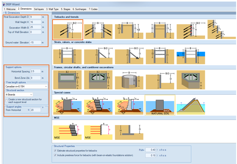
The initial excavation model is generated using the DeepEX model wizard, which allows the engineer to define the main geometry, wall properties, analysis assumptions, supports, and external loads within a structured workflow. For this example, the Limit Equilibrium Analysis method is selected to evaluate the wall response and the stability of the proposed excavation support system.
The analysis settings consider active and passive soil pressures for the cantilever excavation stage and FHWA apparent earth pressures for the supported stages. Groundwater pressures are evaluated using the simplified one-dimensional flow approach, while the beam analysis follows the selected CALTRANS procedure with a 20% negative moment consideration. These settings are maintained throughout the comparison to provide a consistent basis for evaluating the two wall configurations.
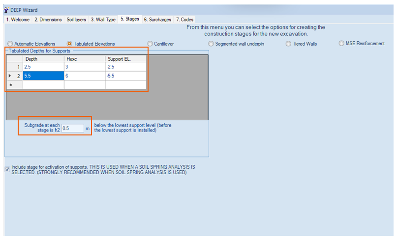
Two levels of tieback anchors are introduced at depths of 2.5 meters and 5.5 meters below the ground surface. The initial fixed length of the anchors is assumed to be 8 meters, while the free lengths are automatically determined using the selected Canadian recommendations. Each anchor is modeled with four strands of 1.5 cm diameter, and the horizontal tieback spacing is 2.5 meters.
The construction sequence is also included in the model. The excavation progresses through successive stages, with the supports installed at the specified elevations and the excavation extending approximately 0.5 meters below each support installation level before the next stage. Modeling the construction sequence is important because the wall behavior, soil pressures, and support reactions change as excavation progresses and the anchors become active.
For the structural design settings, the example uses AISC 360-2022 allowable stress design for steel, ACI 318-2019 for concrete design settings, and service-level geotechnical combinations. The tieback geotechnical safety factor is set to 2, while the selected structural capacity coefficient is 0.6. Once the model is generated, DeepEX can calculate the wall response and perform the relevant structural and geotechnical checks for the examined construction stages.
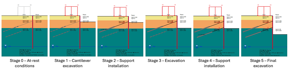
5. Initial Analysis of the Driven Soldier Pile Wall
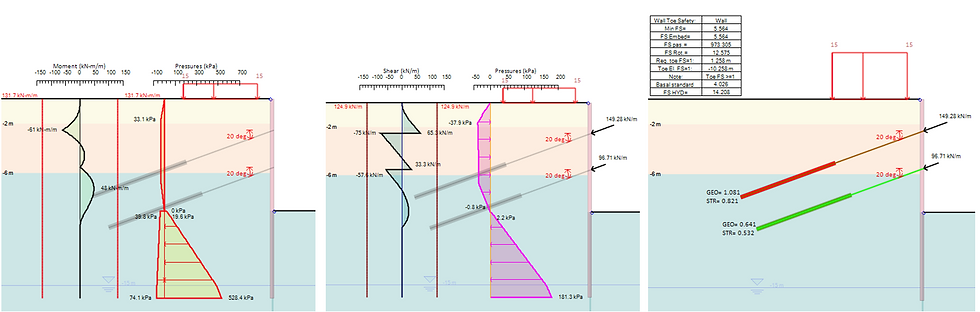
The first analysis is performed for the driven soldier pile wall, using the initially assumed 7-meter embedment. The software calculates the horizontal soil pressures, wall bending moments, shear forces, support reactions, and the corresponding design check results. These outputs allow the engineer to evaluate the behavior of the support system and identify which elements require further investigation.
The initial results indicate a minimum wall embedment safety factor of 5.564. This relatively high value suggests that the preliminary wall embedment is greater than required by the selected stability criterion and that the wall length may be reduced. However, the analysis also identifies a separate problem: the geotechnical pullout capacity of the upper tieback anchor is insufficient to resist the applied load.
This combination of results is important from a design perspective. Although the wall has considerable reserve embedment resistance, the support system does not satisfy every selected check in its initial configuration. Reducing the pile length without addressing the anchor capacity would therefore not provide a complete solution.
The next step is to optimize the wall embedment and the anchor fixed length separately, while reviewing the resulting design checks. DeepEX provides automatic optimization capabilities that can help the engineer investigate these parameters without repeatedly rebuilding the excavation model.
6. Optimization of the Driven Soldier Pile Wall
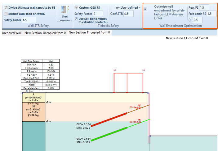
The automatic wall embedment optimization procedure is applied to the driven soldier pile configuration to identify a shorter wall depth that satisfies the selected stability requirements. The optimized wall embedment is calculated as 2.0 meters below the final excavation level, corresponding to a minimum wall embedment safety factor of 1.59.
This result represents a substantial reduction compared with the preliminary 7-meter embedment. For the examined excavation geometry, the total modeled wall length is reduced from 16 meters to 11 meters. The reduction illustrates why preliminary wall dimensions should be reviewed through analysis rather than automatically accepted as the final design.
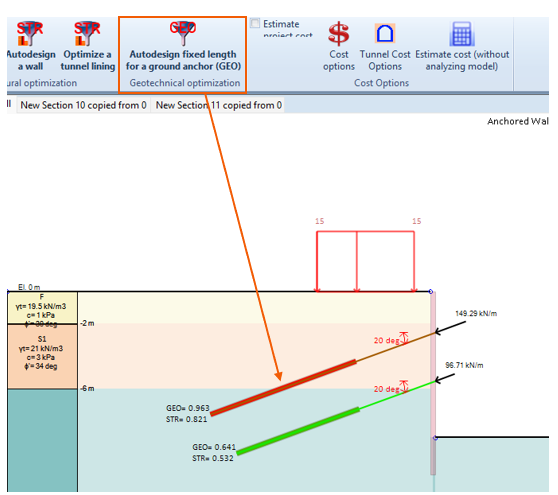
The anchor system is then optimized to address the insufficient pullout resistance identified during the initial analysis. The automatic anchor fixed-length optimization results in a fixed length of 9.5 meters, compared with the initially assumed 8 meters. With this adjustment, the calculated geotechnical check ratio is 0.963, indicating that the optimized anchor satisfies the corresponding selected check.
The driven soldier pile alternative therefore provides an optimized configuration with a 2-meter wall embedment and a 9.5-meter anchor fixed length. This solution establishes the reference against which the drilled and grouted alternative can be compared.
7. Analysis of the Drilled and Grouted Soldier Pile Wall
The second alternative uses the same HE320A steel sections, pile spacing, tieback arrangement, soil properties, and external loads. The difference is that the soldier piles are installed inside 0.5-meter-diameter drilled holes, which are filled with grout or lean concrete.
The wall section properties are adjusted in DeepEX to represent this installation configuration. In the examined model, the drilled and grouted pile has a larger effective width for the mobilization of passive soil resistance below the excavation level. This affects the calculated resisting pressures and, consequently, the wall embedment stability results.
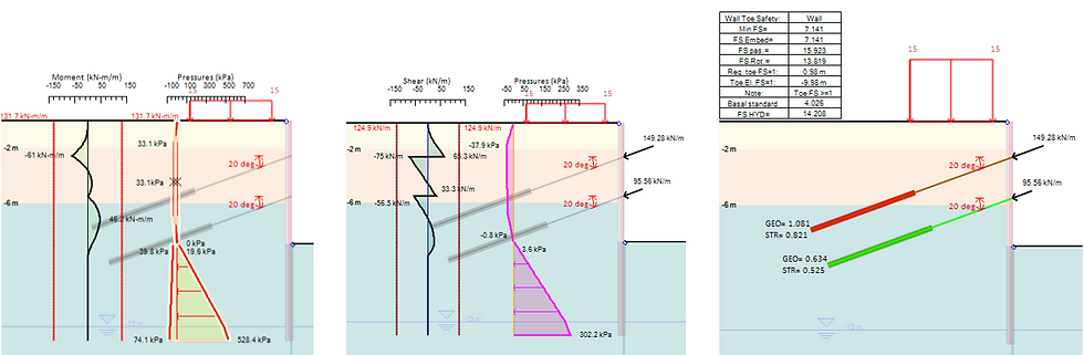
With the initial 7-meter embedment, the drilled soldier pile configuration produces a minimum wall embedment safety factor of 7.141, compared with 5.564 for the driven alternative. This difference indicates that the drilled configuration develops greater modeled embedment resistance under the selected analysis assumptions.
As in the driven pile case, the initial results also indicate insufficient geotechnical pullout capacity for the upper anchor. Consequently, the drilled and grouted solution must undergo both wall embedment optimization and anchor fixed-length optimization before the final configurations can be compared.
8. Optimization of the Drilled and Grouted Soldier Pile Wall
The automatic wall embedment optimization is repeated for the drilled and grouted configuration. The results indicate that the wall embedment can be reduced to 1.5 meters below the final excavation level, while satisfying the selected embedment stability requirement.
The optimized drilled configuration therefore requires 0.5 meters less embedment than the driven pile alternative. This difference is associated with the larger effective passive resistance considered for the drilled and grouted pile in the selected model, rather than a change in the HE320A steel section itself.
The anchor fixed-length optimization produces the same result as the driven configuration. A fixed length of 9.5 meters is required for the upper anchor, with a calculated geotechnical check ratio of 0.963. The results demonstrate that changing the soldier pile installation method affects the optimized wall embedment in this example, while the required anchor fixed length remains unchanged.
For the examined geometry, the optimized drilled wall has a total modeled length of 10.5 meters, compared with 11 meters for the driven alternative. Although the difference is relatively small when expressed as total wall length, it represents a 25% reduction in the optimized embedment below the excavation level.
9. Engineering Comparison: Which Solution Is More Efficient?
The comparison demonstrates that both installation alternatives can be optimized considerably from the initial wall configuration. The driven soldier pile wall achieves an optimized embedment of 2.0 meters, while the drilled and grouted configuration achieves 1.5 meters. Both alternatives use the same HE320A steel section and 2.5-meter pile spacing, and both require a 9.5-meter anchor fixed length to satisfy the examined geotechnical anchor check.
From the standpoint of the selected embedment stability calculation, the drilled and grouted alternative provides an advantage because the larger modeled passive resistance allows a shorter wall. This result illustrates how the effective pile geometry and installation assumptions can influence the design, even when the steel section and support arrangement remain unchanged.
However, a shorter embedment does not necessarily mean a more economical or practical solution. The drilled alternative requires additional construction activities, including drilling, installation of the steel sections, and placement of grout or lean concrete. These operations introduce costs that are not directly reflected in the calculated embedment safety factor.
The driven pile alternative may offer advantages where ground conditions permit efficient driving and where drilling operations would increase construction time or cost. Conversely, drilling may be preferable where driving is difficult or where vibration and noise restrictions are important. The actual selection depends on the available equipment, site accessibility, surrounding structures, subsurface conditions, and project-specific construction requirements.
The engineering comparison should therefore consider the complete support system rather than a single optimized parameter. Wall embedment, steel quantities, anchor lengths, structural demands, geotechnical performance, installation procedures, and construction costs all contribute to the final decision. DeepEX supports this process by allowing the engineer to analyze alternative configurations using consistent assumptions and review the resulting design requirements.
10. Conclusions
This engineering example demonstrates the analysis, design, and optimization of a 9-meter-deep excavation supported by an anchored soldier pile wall, using DeepEX software. Two alternatives were evaluated: driven HE320A steel soldier piles and the same sections installed inside 0.5-meter-diameter drilled and grouted holes.
Starting from a preliminary wall embedment of 7 meters, the analysis identified opportunities to reduce the wall length in both cases. At the same time, the initial calculations revealed insufficient geotechnical pullout resistance for the upper anchor, demonstrating that the optimization process must consider the performance of the complete support system.
Following optimization, the driven soldier pile configuration achieved a wall embedment of 2.0 meters, while the drilled and grouted alternative achieved 1.5 meters. Both alternatives required an optimized anchor fixed length of 9.5 meters. The difference in wall embedment is associated with the different effective passive resistance assumptions used to represent the two installation configurations.
The results demonstrate the value of examining alternative wall configurations during the design process. By allowing engineers to model construction stages, review analysis results, identify critical design checks, and optimize wall and anchor dimensions, DeepEX provides a practical environment for evaluating possible design improvements.
Nevertheless, the configuration with the shortest wall is not automatically the best overall solution. Construction methods, installation costs, site restrictions, and the reliability of the assumed geotechnical parameters must also be considered. The objective of engineering optimization is to identify a safe, practical, and efficient solution for the specific project conditions—not simply to minimize one design dimension.
DeepEX provides the analysis and optimization tools to support this evaluation, while the final selection and verification of the most suitable excavation support system remain the responsibility of the design engineer.

