

What should I use as pressure widths below my excavation in DeepEX?
- May 19
- 2 min read
The driving, resisting, and water pressures exerted on deep excavation walls above ground level are commonly assessed using the wall spacing parameter. Below ground level, it's essential to define the active, water, and pressure widths, taking into account the specific characteristics of the wall type in use.

Wall Section Parameters for each wall type in DeepEX:
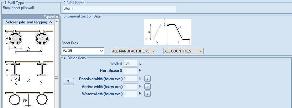
A. Horizontal Spacing (S)
Horizontal spacing is the width of the wall taken into consideration for calculations. It's crucial for accurately distributing calculated moments, shears, etc., presenting results per foot (or meter) of the wall.
A.1. For Continuous walls (such as concrete diaphragms, slurry walls, and sheet piles), it's recommended to use a spacing of 1 foot (or 1 meter).
A.2. For Continuous walls with secant piles, the spacing refers to the center-to-center distance between the reinforced piles.
A.3. For Continuous walls with tangent piles, the spacing indicates the center-to-center distance between each pile.
A.4. For Non-Continuous walls (like soldier piles or combined sheet piles), the spacing denotes the center-to-center distance between each pile.
B. Width (D)
This parameter represents the actual wall width (thickness).
B.1. For Continuous walls such as concrete diaphragms and slurry walls, the width corresponds to the concrete section thickness, defined by the end user.
B.2. For Continuous walls with sheet piles, the width is the equivalent wall thickness, automatically defined by the selected steel section (only graphical).
B.3. For walls with secant, tangent piles, or soldier pile walls supported by reinforced concrete piles, the width equals the diameter of each pile, defined by the end user.
B.4. For soldier pile walls supported by steel sections or combined sheet pile walls:
By default, when using steel sections considered driven, the Width value is defined as the maximum section dimension of the selected steel beam section (Flange - Web) or the steel pipe diameter. If steel sections are used in drilled holes below the excavation with concrete cover, the user can manually adjust the width (D) to define the hole diameter.
C. Active and Water Widths
These are the widths utilized for calculating active and water pressures below the excavation where no lagging is present (applicable for soldier pile walls).
C.1. For Continuous walls (including diaphragms, sheet piles, secant/tangent piles), it's recommended to utilize the wall spacing (as defined above).
C.2. For Non-Continuous walls (such as soldier piles or combined sheet piles), it's recommended to use the Width value (as defined above).
D. Passive Width
This is the width employed for calculating passive pressures below the excavation where no lagging is present (applicable for soldier pile walls).
D.1. For Continuous walls (diaphragms, sheet piles, secant/tangent piles), it's recommended to use the wall spacing (as defined above).
D.2. For Non-Continuous walls (soldier piles, combined sheet piles), it's recommended to use a value between 2.5 to 3 times the Width value (as defined above). However, this value (2.5 or 3*D) is restricted by the defined Spacing. If 2.5 times the Width value exceeds the Spacing, then the Spacing value should be used.
Let us show you how to reduce your design time by up to 90%!


