

Soil Nailing in Weathered Keuper Marl
- Oct 16, 2025
- 6 min read
A Reappraisal Using SnailPlus
Introduction
Baker (1994) describes what is believed to be the first major soil-nailed excavation in the UK, constructed in 1988 at Rover’s Longbridge works. The scheme required a near-vertical excavation, up to 10 m high and 50 m long, to create space for a new paint shop. The excavation was complicated by surcharge loads from nearby structures (a water tank, buildings, and a conveyor bridge), as well as a disused brick-lined tunnel intersecting the retained ground.
To stabilise the face, soil nailing was adopted as a temporary works solution, avoiding the need for more intrusive support systems. This case represents a milestone in UK soil nailing practice, showing how reinforcement could be applied effectively in weak and weathered materials under constrained conditions.
Ground Conditions
The excavation was cut through 6 m of highly weathered Grade IV Keuper Marl, underlain by weathered Keuper Sandstone. The upper 1–1.5 m of the sandstone was completely weathered to sand, and seepages were observed in the excavation, indicating groundwater flow through fissures in the marl.
The effective stress shear strength parameters for the Grade IV Keuper Marl, based on CIRIA Report 47 and site-specific testing, were:
Bulk density: 20–21 kN/m³
Effective cohesion (c′): 10 kN/m²
Effective friction angle (φ′): 28°
Undrained shear strength (su): 100–150 kN/m² (from triaxial tests)
The overlying weathered sandstone was assumed to have c′ = 0 and φ′ = 35°. Drainage measures (deep raking drains and face weep holes) were incorporated to limit pore pressures, although conservative assumptions were applied in design (ru = 0.1 in the nailed zone; ru = 0.25 beneath the tank)
Soil Nail Design and Characteristics
The soil nails comprised 25 mm diameter high-yield deformed steel bars (thread bar type), grouted into 100 mm diameter drilled holes. Grouting was carried out under low pressure, with no additional corrosion protection, as this was a temporary works application.
Key details:
Nail length: typically, 5–8 m beyond potential failure surfaces
· Bond strength: 75 kN/m² adopted (equivalent to 23 kN/m per metre of nail length, assuming 100 mm diameter borehole and grout–soil contact area)
· Vertical spacing: 1.5 m
· Horizontal spacing: 1.5–2.0 m (closer spacing below the surcharge of the water tank, where higher axial capacity was required)
· Inclination: installed with a slight upward rake (~10°) to improve bond mobilisation and drainage.
· Facing: 100 mm shotcrete reinforced with two layers of 100×100×3.7 mm weldmesh, with drainage channels and weep holes incorporated.
The reinforcement layout was designed to resist both local active wedge failures within the nailed zone and overall deeper slip mechanisms passing behind the reinforcement, checked against required and available forces at different elevations.
Reappraisal with SnailPLUS
The case was re-analysed in SnailPLUS using Baker’s reported stratigraphy, soil parameters, and nail geometry. The nails are composed of a 25 mm bar with 10 cm grout. A typical cross-section was modelled with four nail rows, spaced at 1.5 m vertically and 1.5 m horizontally, a 10 cm temporary facing with a single 10x10 (cm2) steel mesh of reinforcement, consistent with the original pattern.
In the present approach, two procedures are considered, one in which the design follows the temporary solution presented in the original study, and another in which a permanent solution is proposed.
In the temporary solution the scheme is as presented in in Figure 1, that illustrates the stratigraphy and the geometry of the problem, and Figure 2 presents the model in SnailPLUS. A water tank is placed on the surface applying a superficial surcharge of 70 kN/m2.

Figure 1- Section considered in the study (from Baker, 1994).

Figure 2- Section modelled in SnailPLUS.
The stability analysis was carried out using the Morgenstern–Price method, which satisfies both force and moment equilibrium along non-circular slip surfaces. For the critical slip surface, the computed factor of safety was 1.09, indicating that the system achieved marginally stable conditions under the assumed parameters. Figure 3 illustrates the results of the safety checks, for Geotechnical and Structural capacity of the soil nails, as well as the slope stability assessment.
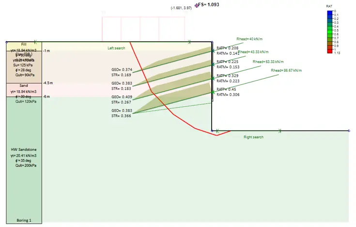
Figure 3- Slope stability analysis results in SnailPLUS.
Table 1 presents the results of the stability analysis, Geotechnical and Structural checks in the soil nail system. Supported by the results in Figure 3, the system passes the safety verifications, but the global stability is compromised because of the safety factor.
Table 1 – Results of safety verification for the temporary solution.
Design | FS | Fmax.Nails | Fmax.Nails | Fmax.Mob | STR Check | STR Check | STR Check | Min. | Max. |
Section | FS Slope | (kN) | Head (kN) | (kN) | Nails | Plates | Facing | Reinf. | Reinf. |
Temporary | 1.093 | 130 | 130 | 185.7 | 0.409 | 0.45 | No | Yes | Yes |
The model showed that excavation at the toe induced a deeper potential slip surface, highlighting the sensitivity of the nailed system to geometry changes. The predicted maximum nail axial forces were within both structural tensile capacity and geotechnical bond resistance, confirming adequate reinforcement distribution.
A modified approach was adopted to enhance long-term stability for a permanent solution. In this design, the facing was extended to the full depth of the excavation, and the soil nail lengths were increased to provide greater reinforcement beyond potential failure surfaces. In addition, the grout characteristics were revised, with a larger diameter adopted to increase the grout–soil contact area, thereby improving bond resistance, pull-out capacity, and the overall durability of the nail system.
Figure 4 presents the layout of the soil nails adopted in the proposed permanent solution, highlighting the extended facing and increased nail lengths designed to enhance long-term stability.

Figure 4- Section modelled in SnailPLUS, for a permanent solution.
With these modifications in the nail configuration, the stability of the excavation improved significantly (Table 2). The extended facing, increased nail lengths, and larger grout diameter provided greater reinforcement and bond resistance, effectively mobilizing higher resisting forces along the critical slip surface. As a result, the analysis of the permanent solution yielded a factor of safety of 1.7, demonstrating a substantial improvement compared to the temporary works design and ensuring a stable long-term performance under the applied surcharge and groundwater conditions.
Table 2 – Results of safety verification for the permanent solution.
Design | FS | Fmax.Nails | Fmax.Nails | Fmax.Mob | STR Check | STR Check | STR Check | Max. | Min. |
Section | FS Slope | (kN) | Head (kN) | (kN) | Nails | Plates | Facing | Reinf. | Reinf. |
Permanent | 1.722 | 230 | 230 | 328.6 | 0.647 | 0.883 | No | Yes | Yes |
Figure 5 presents the results of the stability verifications for the permanent solution. Both geotechnical and structural checks are shown, including the evaluation of the critical slope slip surface obtained from the analysis. The figure highlights the improved factor of safety as well as the distribution of nail forces mobilized to maintain overall stability.

Figure 4- Results of the permanent solution in SnailPLUS.
Discussion
The reappraisal demonstrates several important points for soil-nailed walls:
· Validation of conservative design – SnailPLUS confirmed that Baker’s original parameters and bond strengths were suitably conservative, with results closely matching reported performance.
· Clear insight into failure mechanisms – The software identified how excavation at the toe strongly influenced slip surface geometry, an aspect that would have been harder to visualise with empirical checks.
· Quantifiable benefits of design modifications – The permanent solution increased the factor of safety from 1.09 to 1.7, with SnailPLUS showing exactly how nail length, grout diameter, and facing extent contributed to the improvement.
By combining stability checks, structural verification, and slip surface visualization, SnailPLUS provides a comprehensive tool for engineers to evaluate and refine soil-nailed systems.
Conclusions
This reappraisal of the Longbridge soil nailing project confirms both the ingenuity of the original 1988 design and the benefits of modern numerical verification. SnailPLUS proved to be an effective tool for assessing nail-stabilised walls, offering clear insight into slip surfaces, reinforcement behaviour, and system sensitivity to geometry.
For modern design practice, the key lessons are:
· Conservative parameters are essential when working in weak marls.
· Nail length, spacing, and grout diameter must adapt to surcharges and excavation depth.
· Drainage remains critical for long-term stability.
· Numerical tools like SnailPLUS not only validate empirical design but also enhance understanding, confidence, and optimisation of soil-nailed systems.
Thirty years after Baker’s pioneering work, this case remains a benchmark in UK soil nailing practice — and the use of tools such as SnailPLUS ensures that engineers can design with even greater accuracy and reliability today.
Reference:
Baker, D. A. (1994). Soilnailing in Weathered Keuper Marl — A Case History. Ground Engineering, January/February 1994, 27–33.
Let us show you how to reduce your design time by up to 90%!


