

Example 9: Cantilever TERS in Cohesionless Soil – Bored Soldier Piles
- May 19
- 4 min read
1. INTRODUCTION
This example presents the simulation and analysis of an excavation supported by a cantilevered soldier pile wall. The excavation has a depth of 8 ft and is carried out on loose fine sand, underlain by dense sand. The soil parameters are shown in Figure 1. The groundwater table is located at the base of the excavation, and a uniform surcharge of 360 psf is applied at the surface. The model is developed using DeepEX software and is analyzed using three different methods: Limit Equilibrium, Non-Linear Analysis, and Finite Element Method. The example includes details on the assumed geometry, modelling assumptions, and results obtained from each analysis method.

2. ABOUT DEEPEX
DeepEX is a superior software solution for the design, analysis and optimization of deep excavation projects and tunnels. It has a superior interactive interface that allows the users to generate, analyze, review and evaluate any model fast and in the most efficient way.
Implemented analysis methods: Limit Equilibrium, Non-Linear analysis (soil springs), 2D & 3D Finite Element analysis.
Implemented soil pressure methods (LEM): Active/Passive, At-rest, FHWA Apparent, German EAB, Custom Trapezoidal, 2-step Rectangular, WMATA, NYC and more.
Implemented water pressure methods: Hydrostatic, Simplified flow, Full 2D flownet, Balanced pressures, unconfined flow.
Beam analysis methods (LEM): Blum’s method (continuous beam), FHWA simple span, CALTRANS, WMATA and more.
3. SOIL PROPERTIES
The excavated stratum is a loose fine sand characterized by a friction angle of 30º, moist unit weight of 109.2 pcf, and saturated unit weight of 127.95 pcf. The foundation layer is a dense fine sand with a friction angle of 35º, moist unit weight of 118.37 pcf, and saturated unit weight of 131.13 pcf. Figure 2 presents the soil properties in the input window.


a) b)
Figure 2 – Input window for soil properties definition; a) loose fine sand, b) dense fine sand.
4. WALL SECTION PROPERTIES
The retaining wall is composed of HP14 sheet piles, with the configurations displayed in Figure 3, which presents the geometry, and material properties are described in Figure 4.


Figure 3 – Geometry of the sheet piles section.
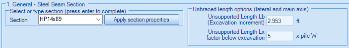
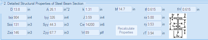

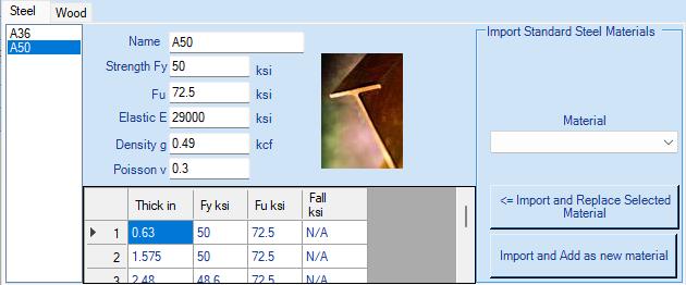
Figure 4 – Sheet piles configurations and material properties.
Below the excavation the steel beams will be placed in grouted boring holes of 2 ft diameter.
5. EXTERNAL LOADS
In the present example, a 360 psf surcharge pressure is applied on the surface, and modelled as a field surcharge (Figure 5).

6. CONSTRUCTION STAGES
The staged construction process allows for controlled excavation and load transfer to the retaining structure, contributing to the stability and safety of the site and its surroundings. The first stage involves the installation of the soldier piles (Figure 6.a), followed by the excavation to the design depth (Figure 6.b)


Figure 6 – Model geometry and loading conditions. Initial phase (a), excavation (b).
7. ANALYSIS ASSUMPTIONS
In the example, the following assumptions were made:
Ground water conditions: Simplified flow.
Active and water width for the calculation of the excavation: equal to the diameter of the pile.
In the passive side: passive width of 2*2.80 = 5.60.
LEM: shear forces, moments and support reaction determined using Blum's method.
In the Non-linear and FEM analyses, the friction between the wall and soil (δ) was set to 33% of the friction angle (ϕ').
For FEM analysis, medium dense sand for Soil Model Behavior (Exponential) (Figure 2).
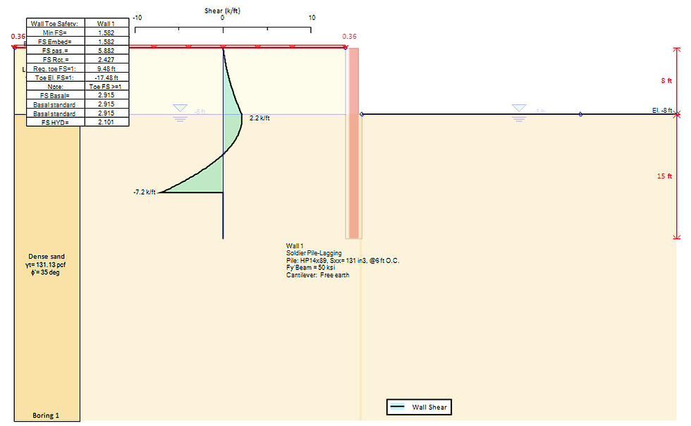
8. DEEPEX ANALYSIS RESULTS
A. Limit Equilibrium Analysis - (show moments and horizontal pressures (Figure 7), shear stress (Figure 8).

B. Non-Linear Analysis - (soil springs) (show moments and horizontal pressures (Figure 9), shear stress and displacements (Figure 10), soil pressures, support reactions)


C. Finite Element Analysis - (same as NL analysis (Figure 10, 11) + FEM Mesh, horizontal (Figure 12) and vertical displacement shadings (Figure 13).


9. ANALYSIS SUMMARY & CONCLUSION
This example involves an excavation supported by a temporary retaining system comprising a cantilevered soldier pile wall. The excavation is 8 ft deep and passes through a layer of loose fine sand underlain by dense fine sand. The preceding sections outline the assumptions adopted for modelling and analysis. The example was modelled and assessed using three analysis methods-LEM, N-L, and FEMavailable in the software DeepEX. The results highlight the software's versatility in delivering reliable design solutions. Table 1 summarises the wall performance verification results, including maximum displacements, bending moments, shear forces, demand-to-capacity ratios, and embedment checks.
Table 1: Critical wall results for each method.

Table notes:
STR Moment: Moment stress check, assuming constant axial load on wall (demand/capacity).
STR Shear: Shear stress check (shear force demand/wall shear capacity).
Let us show you how to reduce your design time by up to 90%!


