

Diaphragm Walls in Deep Excavations
Diaphragm Wall Construction Methods for Deep Excavations
Diaphragm walls are among the most widely used retaining systems for deep excavations in urban environments and infrastructure projects. Their high stiffness, low permeability, and ability to limit ground movements make them particularly suitable for metro stations, underground structures, shafts, and deep basements constructed near existing buildings.
The construction of diaphragm walls requires specialized equipment, strict quality control, and a carefully planned sequence of operations. Because the wall is constructed panel by panel under slurry support, every stage of the process directly affects the structural integrity, verticality, and watertightness of the final system. Compared to other retaining systems, diaphragm wall construction generally requires larger working areas to accommodate cranes, slurry treatment plants, reinforcement cages, and excavation equipment.
Typical Diaphragm Wall Construction Sequence
1. Guide Wall Construction
Guide walls are shallow reinforced concrete elements constructed at the ground surface before trench excavation begins. Although temporary, they are essential for maintaining excavation alignment, panel geometry, and wall continuity.
Their primary functions include:
Maintaining accurate horizontal alignment of the wall
Supporting the upper soil layers during excavation
Guiding the grab or trench cutter vertically
Assisting in reinforcement cage positioning
Providing support during tremie concreting operations
Guide walls are particularly important because the upper portion of the trench is often the least stable, especially as slurry levels fluctuate during excavation.
2. Initial Excavation and Slurry Preparation
Before full-depth excavation starts, the slurry circulation system must already be operational. A shallow starter trench is first excavated and immediately filled with bentonite or polymer slurry so the slurry pump remains fully submerged.
The supporting slurry stabilizes the trench walls by balancing soil and groundwater pressures throughout excavation.
In some projects, localized pre-excavation may also be required before guide wall installation to remove:
Buried obstructions
Existing foundations
Utilities
Old retaining structures
Uncontrolled fill materials
Maintaining proper slurry levels throughout excavation is critical to prevent trench instability or collapse
.

3. Primary Panel Excavation
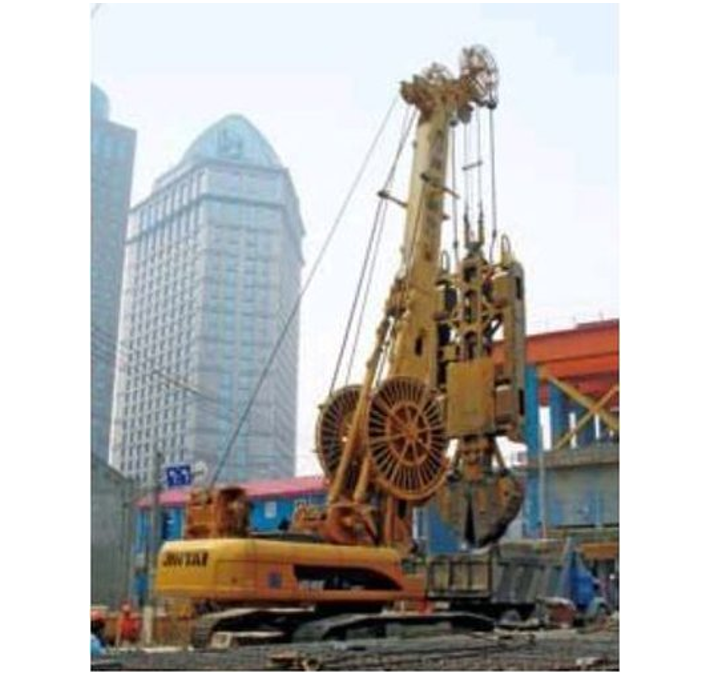
Primary panels are excavated first using mechanical grabs or trench cutters operating under slurry support.
Typical panel lengths range from approximately 2.5 m to 7.0 m depending on:
Excavation equipment
Soil conditions
Wall thickness
Project geometry
In favorable ground conditions, larger panels can be excavated using multiple bites. This method allows the construction of wider panels and more complex geometries such as corner panels and T-panels. Throughout excavation, continuous monitoring of trench verticality and stability is required to maintain acceptable construction tolerances and ensure proper continuity between adjacent panels.
4. Slurry Cleaning and Desanding
The supporting slurry must be continuously monitored and maintained within specified quality limits during excavation and prior to concreting.
The most important slurry parameters include:
Density
Viscosity
Sand content
pH
As excavation progresses, slurry is circulated through a desanding and regeneration plant to remove suspended particles and restore acceptable properties.
Proper slurry cleaning is essential before concreting because contaminated slurry can negatively affect:
Concrete quality
Bond performance
Panel integrity
Joint watertightness
Although fresh slurry may occasionally be introduced, slurry regeneration is generally more economical and environmentally efficient.
5. Joint Construction Methods
Panel joints are critical elements in diaphragm wall construction because they influence both structural continuity and groundwater control.
Several joint systems are commonly used, including:
Flat joints
Circular stop-end joints
Steel beam joints
Grooved water-stop joints
Joint selection depends on:
Contractor preference
Excavation equipment
Groundwater conditions
Project performance requirements
Grooved joints with integrated water stops are often preferred because they improve interlock and reduce seepage potential. In North America, steel I-beams are also widely used as stop-end elements and water barriers. Simpler flat joints are generally less effective for projects with demanding groundwater control requirements.
6. Reinforcement Cage Installation and Tremie Concreting
Once the excavation reaches the design depth and the trench bottom is cleaned, the reinforcement cage is lifted and lowered into the slurry-filled panel.
Because cages are often extremely long and heavy, they must contain sufficient transverse and diagonal reinforcement to maintain stiffness during lifting and placement.
Adequate spacing must also be provided for multiple tremie pipes.
Tremie Concreting
Concrete placement is performed using tremie pipes extending to the bottom of the trench. The concrete is placed from the bottom upward, progressively displacing the supporting slurry.
To prevent contamination and segregation:
The tremie pipe tip must remain continuously embedded in fresh concrete
A minimum embedment of approximately 0.6 m (2 ft) is typically maintained
Additional overpouring is commonly required to ensure complete slurry displacement
Poor tremie practices may trap slurry pockets within the wall, potentially leading to:
Groundwater leakage
Reduced durability
Honeycombing
Structural defects
Localized blowouts
Such issues have contributed to major repairs and delays in several large infrastructure projects, including portions of Boston’s Central Artery / Tunnel Project (“Big Dig”).

7. Secondary Panel Excavation
After the primary panels gain sufficient strength, secondary panels are excavated between them to complete the continuous wall system.
When trench cutters are used, the cutter trims into the edges of adjacent primary panels to create a clean interface and improve continuity between panels.
After excavation:
The trench is cleaned
The reinforcement cage is installed
Tremie concreting is performed from the bottom upward
The alternating sequence between primary and secondary panels continues until the entire diaphragm wall perimeter is completed.
Construction Challenges and Quality Control
Successful diaphragm wall construction depends heavily on field quality control and experienced execution.
The most common construction challenges include:
Trench instability
Loss of slurry
Excessive trench deviation
Joint defects
Reinforcement cage instability
Poor slurry properties
Concrete contamination during tremieing
Groundwater leakage through joints
To minimize these risks, continuous monitoring is typically performed for:
Slurry properties
Verticality
Panel depth
Reinforcement cage alignment
Concrete volume and tremie embedment
Joint positioning
Strict quality assurance procedures are especially important in urban excavations where wall movements and groundwater inflow can directly affect adjacent structures and utilities.
Modeling Recommendations for Diaphragm Wall Analysis
Reliable diaphragm wall analysis requires realistic representation of soil behavior, groundwater conditions, construction sequencing, and soil–structure interaction.

Key modeling recommendations include:
Define realistic soil stratigraphy, including weak layers and groundwater conditions
Use appropriate constitutive models based on the required level of analysis (e.g., Mohr-Coulomb
for preliminary studies and Hardening Soil models for advanced analysis)
Simulate excavation and support installation sequentially to capture staged construction effects
Properly model wall stiffness, interfaces, and support systems
Include groundwater pressures and seepage effects, particularly for deep excavations below the water table
Refine the numerical mesh near wall interfaces, excavation bottoms, and support connections
Evaluate both structural capacity and serviceability performance, including wall deflections and ground settlements
Validate numerical results using analytical methods, field data, or comparisons between LEM, beam-spring, and FEM approaches
Perform sensitivity analyses for key parameters such as soil stiffness, groundwater level, and support stiffness
Advanced numerical tools such as the DeepEX platform allow engineers to combine staged excavation analysis, groundwater modeling, and soil–structure interaction within a unified workflow, improving both design efficiency and project reliability.
Let us show you how to reduce your design time by up to 90%!


