

Helical Pile Design Verification - Pipe with Casing & Grout
- Dec 27, 2023
- 3 min read
Updated: Apr 28
3'' Pipe with External Casing and Grout with 8''-10''-12'' Helixes
A. Project description
This example presents a detailed example for calculating the ultimate axial capacity of a helical pile according to Vesic 1974 and Meyerhoff/Hansen method. Table 1 below presents assumed soil properties, Table 2 summarizes the soil stratigraphy, while Table 3 describes assumed helical pile properties.
Table 1: Soil properties

Table 2: Stratigraphy (Boreholes)

Table 3: Helical pile properties

We will examine three cases:
The pile as described in the previous table
The use of an external casing (Diameter: 8'' , length: 12 ft)
The use of an external casing as described above and 6'' grout extended to 8 ft from the pile bottom.

Soil Properties and Model in HelixPile

Pile Section Properties and Helix Configuration
B. Ultimate bearing capacity calculations – Cylinder failure method
B1. Manual calculations
For the cylinder latteral pressures factor, we will use the Mitch – Clemence method:
K = 0.09e(0.08fr) = 1.366
Table 4: Ultimate shear stress line force calculations.


Figure: Ultimate shear stress line force on cylinder body.
Cylinder strength: Fcylinder = A1 + A2 = 14120.725 + 9867.31 = 23988.035 lbs = 23.99 kips
Vesic method
Tip: Fult = 2.45 kips (compression)
Plate 1: Fult = 15.24 kips (compresion)
Plate 3: Fult = 32.95 kips (tension)
So, the utimate cylinder compression capacity is Fult, comp = 23.99 + 2.45 + 15.24= 41.68 kips
The utimate cylinder tension capacity is Fult, tension = 23.99 + 32.95 = 56.94 kips
Meyerhoff/Hansen
Tip: Fult = 3.32 kips
Plate 1: Fult = 20.62 kips
Plate 3: Fult = 44.59 kips
So, the utimate cylinder compression capacity is Fult, comp = 23.99 + 3.32 + 20.62 = 47.93 kips
The utimate cylinder tension capacity is Fult, tension = 23.99 + 44.59 = 68.58 kips
Ultimate shaft capacity calculations:
Case I (no grout, no external casing)
Table 5: Shaft resistance calculation parameters – Case I

Table 6: Shaft resistance calculations – Case I

Fshaft = A1+A2+A3+A4 = 7957.66 lbs = 7.96 kips

Figure: Shaft resistance diagram
Case II (external casing 8'' , no grout)
Table 7: Shaft resistance calculation parameters – Case II

Table 8: Shaft resistance calculations – Case II


Figure: Shaft resistance diagram
Fshaft = A1+A2+A3+A4+A5 = 10496.89 lbs = 10.5 kips
Case III (external casing 8'' , grout 6'')
Table 9: Shaft resistance calculation parameters – Case III

Table 10: Shaft resistance calculations – Case III

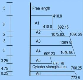
Figure: Shaft resistance diagram
Fshaft = A1+A2+A3+A4+A5+A6 = 17573.71 lbs = 17.57 kips
Table 11: Shaft and cylinder tension capacity – Vesic method

Table 12: Shaft and cylinder compression capacity – Vesic method

Table 13: Shaft and cylinder tension capacity – Meyerhoff/Hansen method

Table 14: Shaft and cylinder compression capacity – Meyerhoff/Hansen method

B2. Calculations with HelixPile

Figure: Compression and tension cylinder method results in HelixPile (Vesic method – Case I)

Figure: Compression and tension cylinder method results in HelixPile (Meyerhoff/Hansen method – Case I)

Figure: Compression and tension cylinder method results in HelixPile (Meyerhoff/Hansen method – Case II)

Figure: Compression and tension cylinder method results in HelixPile (Vesic method – Case III)

Figure: Compression and tension cylinder method results in HelixPile (Meyerhoff/Hansen method – Case III)
Table 15: Comparison between manual calculations and HelixPile results.


Book A free web presentation:


