

Pile Group Load Tests by Matlock et al. 1980
- Nov 4, 2023
- 3 min read
Updated: Apr 29
Field Tests of Lateral Load Behavior of Pile Groups in Soft Clay
A. INTRODUCTION
In 1980 at Harvey, Louisiana, a number of experiments were performed by Matlock et al. [1] examining the lateral behavior of pile groups in soft clay. The experimental case study included static and cyclic lateral load tests of single piles, five-pile circular groups and ten-pile circular groups of six-inch diameter pipe piles. Deflections were enforced at two elevations by a special loading device to simulate pile-head restraints typical of offshore structures as illustrated in figure 1b. The authors reported measurements of the total load and deflection of the groups and additionally the individual pile shears and bending moments of selected piles (fig 1.a).

Figure 1: a) Arrangement of equipment for field tests b) Driver mechanism and spool for loading the piles (Matlock et al 1980)
B. MODEL OF THE FULL-SCALE TESTS IN DEEPFND
The DeepFND P-Y method is used for the simulation of the Matlock single pile and pile group full scale tests. For the single pile analysis, a fixity to rotation was imposed at the top of the pile. The pile moment of inertial was calculated to be equal to I=1.17x10⁻⁵m4. The strength of the soil at the top of the pile was computed to be Su=15Kpa gradually increasing up to Su=35.2Kpa at a depth of 12m. The strength properties of the soil are in accordance with the measured undrained strength values from in-situ vane tests and laboratory undrained triaxial tests included in [1]. Soil stiffness properties are generated based on the proposed value recommendation of e50 in the literature. The DeepFND Model and the results of the analysis are illustrated in Figure 2.

Figure 2: Single Pile a) Model in DeepFND b) Deflection and moment measurements comparison with model results
For the simulation of the pile group tests a circular pile cap in the dimensions of the spool was used. As portrayed in figure 1 the axis of the test spool was constrained by the ball-screw jacks to remain very nearly vertical. The same behavior is emulated in the DeepFND model by the introduction of 2 additional vertical springs on the pile cap constraining the pile cap from any rigid rotation. Group effects are considered based on the default interaction factor method included in the software relative to the load direction. The DeepFND Model and the results of the analysis are illustrated in Figure 3 and Figure 4 for the 5 pile group and 10 pile group respectively.
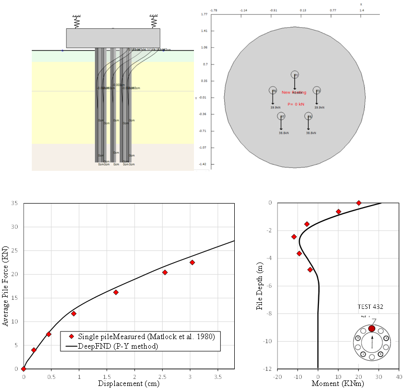
Figure 3: 5 Pile Circular Group a) Model in DeepFND b) Deflection and moment measurements comparison with model results

Figure 4: 10 Pile Circular Group a) Model in DeepFND b) Deflection and moment measurements comparison with model results
The group effect for the 5 pile and 10 pile foundations is illustrated in Figure 5.

Figure 5: Comparative Results
D. CONCLUSIONS
The P-Y method implemented in DeepFND is capable of accurately capturing the pile-to-pile interaction effects for arbitrary shapes of pile layout within a pile group foundation. The accuracy of the model is mainly influenced by the correct consideration of soil strength properties at a primary level, while soil stiffness properties could also affect the results, however in a smaller scale.
E. REFERENCES
[1] Matlock, Hudson, Ingram, Wayne B., Kelley, Allen E., and Dewaine Bogard. "Field Tests Of The Lateral-Load Behavior Of Pile Groups In Soft Clay." Paper presented at the Offshore Technology Conference, Houston, Texas, May 1980.


