top of page
Slope stability analysis and soil nail wall design with SnailPlus

Clouez-le bien : Votre compagnon expert pour des conceptions de parois clouées au sol sans faille et efficaces

Apprenez à concevoir des murs de clous de sol en quelques minutes !

1

À propos

SnailPlus 2024 - Logiciel d'analyse de clous de sol.

Conception structurelle complète de tous les éléments : Clous de sol, revêtement en béton projeté, plaques de tête.

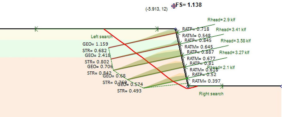
Slope stability analysis results in SnailPlus software

SnailPlus est notre logiciel d'analyse de stabilité des pentes et de conception de murs cloués. Bien que le clouage de sol soit également disponible dans notre programme DeepEX, SnailPlus a été créé pour rassembler toutes les capacités nécessaires en un seul paquet.


Le logiciel suit la méthodologie de la FHWA pour la conception des murs cloués, dans un environnement interactif basé sur la disposition de base de DeepEX. Cela signifie que vous pouvez inclure toutes les étapes de construction intermédiaires pour votre mur cloué, y compris les charges 3D, le tout dans un environnement interactif.


Enfin, SnailPlus est le seul logiciel qui produit un rapport imprimable complet de tous les calculs de conception.

Tunnel analysis in DeepEX

The procedure to create and analyze any quay wall type within the program is summarized in the following steps:

1. Create the Quay Wall model with the use of the powerful Model Wizard in minutes with all construction stages. 

2. Edit the Quay Wall structural section. 

3. Edit the soil properties and stratigraphy. 

4. Define the analysis assumptions, wave pressures and overtopping methods, and the seismic pressures method.

5. Review the results in graphs and tables on the model area for all construction stages and optimize the model.

SCHEDULE A FREE WEB DEMO

Interface interactive intuitive

Modélisation graphique

Polyvalence dans les entrées de charge

Personnalisation et flexibilité

Analyse exhaustive

Rapports détaillés

2

Avantages

POURQUOI CHOISIR SNAILPLUS ?

Quoi de neuf dans SnailPlus 2024 ?

Export soil nail wall model sketches to DXF in SnailPlus

Exportez des croquis de modèle de mur de clous de sol au format DXF dans SnailPlus Nous sommes fiers d'annoncer que SnailPlus 2024 est arrivé ! La dernière version de notre logiciel est un témoignage de notre engagement envers l'innovation. La génération de tranches améliorée pour des intersections de couches précises, les codes de béton mis à jour et les sorties de rapport améliorées soulignent notre dévouement à affiner chaque aspect de l'expérience utilisateur. Avec des options de l'épaisseur de la face variable, l'introduction de clous de sol précontraints et des combinaisons de charges mises à jour selon les codes de l'AASHTO et canadiens, SnailPlus 2024 établit une nouvelle norme pour l'analyse de la stabilité des pentes.

Améliorations et nouvelles fonctionnalités de SnailPlus 2024 :

 Génération de tranches améliorée pour des intersections de couche exactes

 Codes de béton mis à jour

 Combinaisons de charges selon les codes de l'AASHTO et canadiens mis à jour

 Génération de l'assistant améliorée

 Sorties de rapport améliorées

 Options de l'épaisseur de la face variable

 Clous de sol précontraints

 Dessins de sortie au format DXF

3

Nos tutoriels

COMMENT FONCTIONNE LE LOGICIEL SNAILPLUS ?

4

Caractéristiques

CARACTÉRITIQUES PRINCIPALES ET CAPACITÉS DE SNAILPLUS

  • INTERFACE INTERACTIVE SUPÉRIEURE
    SnailPlus est un logiciel extrêmement convivial, qui offre une interface de modèle interactive. Dans la zone du modèle, nous pouvons créer toutes les étapes et définir tous les paramètres du projet (charges externes, sections de clous de sol, sections de béton projeté, etc.) graphiquement. Tous les éléments de la zone du modèle (sondages, clous de sol, revêtement) peuvent être accédés et leurs propriétés peuvent être définies via des boîtes de dialogue conviviales.
  • EXPORTATION DES RAPPORTS EN PDF ET EN MS WORD
    Les rapports de SnailPlus peuvent inclure des tableaux et des graphiques avec toutes les propriétés du modèle examinées et les résultats calculés. Nous pouvons également choisir d'inclure dans le rapport toutes les équations de conception structurelle et la procédure de calcul. Les rapports de SnailPlus peuvent être prévisualisés, exportés au format PDF ou exportés au format Word, afin qu'ils puissent être modifiés ultérieurement par l'utilisateur. Sélectionner les sections de conception à rapporter Sélectionner les étapes de construction à rapporter Personnaliser les graphiques du rapport Définir la mise en page du rapport Définir les sections du rapport Possibilité de rapporter les équations et les calculs d'étape Aperçu du rapport Exporter les rapports au format PDF et Word
  • PROPRIÉTÉS DU SOL - ENREGISTREMENTS SPT - JOURNAUX CPT
    Les types de sol, les propriétés du sol et les stratigraphies peuvent être facilement définis dans SnailPlus grâce à des boîtes de dialogue conviviales. Dans SnailPlus, nous pouvons créer une liste illimitée de sols et définir rapidement toutes les propriétés du sol. Le logiciel fournit plusieurs outils d'estimation (estimateur SPT et outils d'estimation partielle pour chaque propriété à l'aide de méthodes et d'équations scientifiques). Dans SnailPlus, nous pouvons ajouter directement des enregistrements SPT et des journaux CPT, qui peuvent être utilisés à partir du logiciel pour estimer diverses propriétés du sol. Définir la liste des types de sol Définir la liste des stratigraphies (sondages) Outils d'estimation des propriétés du sol Enregistrements SPT Journaux CPT
  • Modèle Wizard - Créez un modèle en quelques secondes
    Modèle Wizard de SnailPlus peut être utilisé pour créer n'importe quelle surface inclinée avec toutes les étapes de construction, les excavations, l'installation de clous de sol et de revêtements en quelques minutes. Nous pouvons utiliser les onglets de l'assistant pour définir tous les paramètres du projet (paramètres de la surface inclinée, clous de sol - plaques de tête et sections structurales en béton projeté, options d'étape et normes de conception). L'Assistant crée automatiquement le modèle, nous faisant gagner beaucoup de temps et d'efforts pour la création initiale.
  • CODES DE CONCEPTION STRUCTURALE ET GÉOTECHNIQUE
    HelixPile a mis en œuvre de nombreux codes et normes internationaux de conception pour la conception et l'analyse (structurelle et géotechnique) des pieux hélicoïdaux. Dans HelixPile, nous pouvons effectuer une conception de service ou une conception avec facteurs en utilisant les normes américaines et européennes. Nous pouvons facilement sélectionner et changer entre plusieurs codes structurels américains, européens, australiens et chinois. ACI 318-11 (Éléments en béton armé) ASD 1989 (Conception par contraintes admissibles - Éléments en acier) AASHTO LRFD 13e édition (Éléments en acier) AISC 360 et 360-Admissible (2010 et 2016) Spécifications EUROCODE 2, 7 et 8 Combinaisons de charges AASHTO LRFD Codes européens (DIN, BS, XP94, DM, DA) Normes australiennes (AS 3600, AS/NZS 4100) Normes chinoises (CN)
  • GROUPES DE PIEUX - RADIERS SUR PIEUX
    HelixPile peut concevoir à la fois des pieux hélicoïdaux simples et des groupes de pieux avec plusieurs pieux (le module optionnel supplémentaire Groupes de Pieux est requis). Le logiciel peut également concevoir des radeaux de pieux, considérant l'effet combiné du sol sous le radeau (module supplémentaire à notre option de groupe de pieux). Pieux hélicoïdaux simples Caps de pieux rectangulaires Caps de pieux triangulaires Caps de pieux circulaires Caps de pieux hexagonaux Caps de pieux octogonaux Caps de pieux avec périmètre défini par l'utilisateur Radeaux de pieux
  • TYPES DE PIEUX & CONFIGURATIONS HELIX
    HelixPile peut effectuer la conception complète verticale et latérale des pieux hélicoïdaux. Les pieux hélicoïdaux dans HelixPile peuvent être de toute forme typique (tuyaux, sections carrées pleines et sections creuses carrées). Dans chaque pieu, nous pouvons définir et attribuer un nombre illimité de configurations d'hélice. Les pieux peuvent être scellés. Enfin, nous pouvons utiliser un boîtier externe sur la tête du pieu, augmentant la capacité latérale du pieu. Tuyaux en acier Sections carrées en acier solide Sections creuses carrées en acier Configurations illimitées d'hélice par pieu Pieux scellés Utilisation d'un boîtier en acier externe
  • ANALYSE AXIALE & LATÉRALE DES PIEUX
    HelixPile peut effectuer à la fois des analyses de pieux verticaux et latéraux. HelixPile utilise à la fois les méthodes de la plaque individuelle et du cylindre, rapportant les résultats les plus critiques. On peut choisir entre les équations générales et Helicap. Pour la conception de pieux verticaux, nous pouvons choisir d'utiliser soit la méthode de Vesic, soit celle de Meyerhoff-Hansen. HelixPile calcule et vérifie le couple d'installation des pieux hélicoïdaux. Pour l'analyse latérale des pieux, HelixPile peut utiliser soit la charge définie sur la tête du pieu et calculer les diagrammes de moment développé, de cisaillement et de déplacement du pieu, soit effectuer une analyse de poussée, calculant et présentant la charge latérale requise pour atteindre un déplacement spécifié de la tête du pieu. HelixPile peut effectuer une analyse de tassement. Dans le logiciel, nous pouvons sélectionner l'un des critères d'acceptation des pieux implémentés, ou définir notre propre critère.
  • INTERFACE INTERACTIVE SUPÉRIEURE
    HelixPile est un logiciel extrêmement convivial, qui offre une interface de modèle interactive. Dans la zone de modèle, nous pouvons créer différentes étapes de chargement et définir tous les paramètres du projet (charges externes sur la tête du pieu, propriétés de la section du pieu, etc.) graphiquement. Tous les éléments dans la zone de modèle (forage, pieu, charges externes) peuvent être accessibles et leurs propriétés peuvent être définies à travers des dialogues conviviaux.
  • RAPPORTS EXPORTÉS EN PDF & WORD
    HelixPile peut générer des rapports étendus pour toutes les sections de conception examinées (pieux) et les étapes de chargement. Les rapports dans HelixPile sont totalement personnalisables - l'utilisateur final peut toujours sélectionner toutes les sections du rapport incluses dans le rapport final. Les rapports HelixPile peuvent inclure des tableaux et des graphiques avec toutes les propriétés du modèle examiné et les résultats calculés. Nous pouvons également choisir d'inclure dans le rapport toutes les équations de conception structurelle et la procédure de calcul. Sélectionnez les sections de conception à rapporter Sélectionnez les étapes de construction à rapporter Personnalisez les graphiques du rapport Définissez la mise en page du rapport Définissez les sections du rapport Possibilité de rapporter les équations et les calculs des étapes Aperçu du rapport Exporter les rapports en formats PDF et Word
  • GÉNÉRATION ET OPTIMISATION AUTOMATIQUE DE MODÈLES DE VÉHICULES
    Le modèle de HelixPile peut être utilisé pour créer n'importe quel modèle de fondation profonde en quelques minutes. Nous pouvons utiliser les onglets du modèle pour définir tous les paramètres du projet (paramètres d'analyse, type de pieu et section structurelle, charges externes et normes de conception). Le modèle crée automatiquement le modèle, nous faisant gagner beaucoup de temps et d'effort pour la création initiale. HelixPile dispose d'un outil d'optimisation automatique de la longueur. Le logiciel peut utiliser une étape définie pour augmenter la profondeur du pieu jusqu'à une limite de profondeur définie, calculant la capacité de tension axiale et de compression à chaque étape.
  • PROPRIÉTÉS DU SOL - ENREGISTREMENTS SPT - JOURNAUX CPT
    Les types de sols, les propriétés des sols et les stratigraphies peuvent être facilement définis dans HelixPile à travers des dialogues conviviaux. Dans HelixPile, nous pouvons créer une liste illimitée de sols et définir rapidement toutes les propriétés du sol. Le logiciel offre plusieurs outils d'estimation (estimateur SPT et outils d'estimation partielle pour chaque propriété en utilisant des méthodes et des équations scientifiques). Dans HelixPile, nous pouvons ajouter directement des registres SPT et des journaux CPT, qui peuvent être utilisés par le logiciel pour estimer diverses propriétés du sol. Définir la liste des types de sol Définir la liste des stratigraphies (forages) Outils d'estimation des propriétés du sol Registres SPT Journaux CPT
  • TYPES DE MURS MULTIPLES
    Le logiciel QuayWalls peut concevoir tout type de section de mur de quai de gravité, calculant les pressions du sol, de l'eau, des vagues et sismiques sur le système de mur. QuayWalls peut être utilisé pour la conception et l'analyse de : Murs en porte-à-faux Murs segmentés Murs de caisson en boîte avec zones de remplissage de sol Murs en forme de T Murs définis par l'utilisateur
  • PRESSIONS DES VAGUES ET DÉBORDEMENT
    QuayWalls peut calculer les pressions des vagues en utilisant plusieurs méthodes établies. Les hauteurs initiales des vagues et les longueurs d'onde peuvent être estimées à l'aide de recommandations intégrées, ou définies manuellement par l'utilisateur via un dialogue convivial. Enfin, QuayWalls peut estimer automatiquement les débits de débordement car il peut effectuer des calculs de volume de débordement moyen en utilisant les équations de PROVERBS. Goda SainFlou Manuel d'Ingénierie Côtière 2011 Allsop PROVERBS
  • ANALYSE DE STABILITÉ DES PENTES ET CONCEPTION DE CLOUS DE SOL
    SnailPlus stabilité globale des surfaces de pente (simples ou renforcées par des clous de sol). SnailPlus peut calculer et rapporter la surface de pente la plus critique et le facteur de sécurité de la stabilité de la pente en utilisant plusieurs méthodes scientifiques. Les clous de sol peuvent être utilisés sur les surfaces de pente. SnailPlus calcule les effets des clous de sol sur l'analyse de la stabilité de la pente. Méthode Bishop Méthode Morgenstern-Price (Équilibre Limite Général) Méthode Spencer Normes françaises Clouterre pour la conception des clous de sol
  • CONCEPTION COMPLÈTE DU REVÊTEMENT EN SHOTCRETE
    SnailPlus peut concevoir le revêtement en shotcrete. Des revêtements en deux étapes (temporaires et permanents) peuvent également être définis et analysés avec le logiciel. SnailPlus effectue des vérifications sur les plaques de tête des clous de sol. Conception du revêtement en shotcrete Revêtement en deux étapes disponible Vérifications des plaques de tête
  • CODES ET SPÉCIFICATIONS DE CONCEPTION
    SnailPlus a implémenté diverses normes et spécifications pour la conception des clous de sol et des revêtements en shotcrete. Dans SnailPlus, nous pouvons sélectionner les spécifications ACI et FHWA pour la conception structurelle. Dans le logiciel, nous pouvons utiliser des méthodes d'État Limite de Service ou d'État Limite Ultime. ACI Direct method FHWA and FHWA LRFD methods LRFD WSDOT 2019 (GDM) ASD Safety factors LRFD FHWA GEC-7 EUROCODE 7 - ULS Approach
  • OPTIONS DE RECHERCHE DE SURFACES DE PENTE MULTIPLES
    SnailPlus peut localiser et rapporter la surface de pente la plus critique en utilisant diverses méthodes de recherche de surfaces de pente : Surfaces de Pente Circulaires Surfaces Circulaires avec des Coins Actifs et/ou Passifs Méthode de Recherche de Surface Automatique Méthodes de Recherche de Surface Trilinéaire Surfaces avec défaillance de type bloc Surfaces de Pente Définies par l'Utilisateur
  • What is the difference between DeepFND and HelixPile?
    DeepFND and HelixPile are two similar, powerful software programs for the design and evaluation pile foundations. The programs can perform structural and geotechnical, lateral, and axial analysis of any foundation pile (single piles, pile groups and pile rafts).The only difference between the two programs is the available pile types. DeepFND can design all pile sections and pile types (helical and non-helical – drilled, driven, caissons, micropiles, CFA piles and more), whereas HelixPile can design only helical piles.
  • Does your program check the structural capacities of the piles as well?
    DeepFND and HelixPile software have implemented several structural codes used worldwide. The software do all calculations according to the selected standard and calculate the pile moment and shear capacities. All structural design checks and equations can be included in the software reports. Figure: Pile Moment, Shear and Displacement Diagrams - DeepFND
  • Can your software design pile caps with a group of piles?
    Our foundation pile design software can design single foundation piles, pile groups and pile rafts. The following pile cap shapes are available: Rectangular Pile Caps Triangular Pile Caps Circular Pile Caps Hexagonal Pile Caps Octagonal Pile Caps User-Defined Perimeter Pile Caps Pile Rafts The user can create a concrete cap of any shape and define the pile configuration (pile locations and structural sections). The program can calculate the load that is transfered on each pile, considering the pile location and analyze all piles. Figure: A Rectangular Cap with Concrete Piles - DeepFND Figure: A Circular Cap with Helical Piles - DeepFND and HelixPile
  • What type of Pile Analysis can your software do?
    Our foundation piles design software DeepFND and HelixPile can perform axial and lateral analysis of any pile type. The programs can calculate the pile shaft resistance and the bearing capacity of the piles, taking into consideration the pile installation method. In addition, the software can do lateral pile analysis, calculating the pile displacements, moment and shear diagrams for any applied load combination on the pile head.
  • How is the pile cap modelled, rigid or finite stiffness?
    The pile cap is modelled with quadrilateral shell finite elements. The user can post process stress resultants and displacement of the cap.
  • What type of loads can i add on a single pile?
    In DeepFND and HelixPile software, we can add axial loads, lateral loads and external moments on both directions on each single pile head. In addition, we can add a distrubuted lateral load along the pile (user-defined elevations and magnitude). The following list summarizes the loads that can be applied on each axis. - Axial Loads (Z Axis) In DeepFND and HelixPile we can add axial loads on the pile head. A positive axial load magnitude is a compression load (downwards) and a negative magnitude is a tension load (uplift). - Lateral Loads (X Axis) The X-Axis is along the screen. A positive magnitude is a left-to-right load, and a negative magnitude is a right-to-left load. - Lateral Loads (Y Axis) The Y-Axis is on the perpendicular direction of the screen. A positive magnitude is an inwards load, and a negative magnitude is an outwards load (from the screen to the user). - External Moments (X and Y Axis) The external moments on each direction can be defined for each stage. A positive moment magnitude is a counter-clockwise moment, a negative value is a closkwize moment.
  • Which structural section types can i use in DeepFND?
    DeepFND software is designed to handle a wide variety of pile types, making it versatile and efficient for deep foundation design and analysis. Within minutes, the software can perform both axial and lateral pile analysis, as well as structural design for different types of piles. Whether you're working with traditional or more specialized pile systems, DeepFND offers robust design capabilities. One of DeepFND’s key features is its ability to recognize the material type of the pile and automatically apply the relevant structural code. These include major standards such as the International Building Code (IBC), AASHTO, ACI, Eurocode 2, Eurocode 3, NTC, AISC, Canadian standards, Australian codes, Chinese codes, and many more. This ensures that the software computes structural capacities accurately and performs all required structural checks in compliance with the selected code. Pile Types Available in DeepFND DeepFND provides users with a comprehensive range of pile types and configurations. These can be quickly defined using the model wizard, where you can specify wall section properties such as dimensions, reinforcement, and material characteristics. Below are the main pile types that DeepFND supports: 1. Helical Piles Supported shapes: Pipes, square solid, and square hollow sections. In DeepFND, helical piles can be customized with an unlimited number of helix configurations to meet your project requirements. Additional options: You can choose to grout the piles for improved capacity and apply external casing to the pile head to further enhance its lateral capacity. 2. Non-Helical Piles Types: DeepFND supports a variety of common piles, including drilled shafts, driven piles, CFA piles, caissons, and more. Shapes: These piles can be modeled in different geometric forms such as circular, square, hollow, and octagonal sections. Materials: You can simulate piles made from reinforced concrete, structural steel, or timber (wood). Special configurations: Non-helical piles can also be designed as belled piles for increased bearing capacity at the base. In addition, DeepFND allows for composite pile sections where the shape or material of the pile can change along its depth. For timber piles, the software can generate tapered sections to account for naturally varying dimensions. 3. Stone Columns Stone columns are another type of foundation that DeepFND can simulate, including configurations with mechanically stabilized earth (MSE) grids such as geotextiles and geogrids to reinforce the structure. Full List of Supported Pile Types: Helical piles (pipes, square solid, or square hollow sections) Reinforced concrete piles (circular or square sections) Prestressed concrete piles, including those with GFRP (Glass Fiber Reinforced Polymer) or CFRP (Carbon Fiber Reinforced Polymer) reinforcements Steel piles (H-piles, pipes, channel sections) Belled type piles Timber piles (tapered or straight wood piles) Steel core piles Composite piles (with varying sections along the depth) Stone columns with MSE grid reinforcement DeepFND’s comprehensive suite of supported pile types and configurations ensures that it can meet the demands of any deep foundation project, providing the flexibility and precision needed for modern engineering designs. Whether you're designing simple or complex foundations, the software is equipped to handle your project with ease.
  • Can i check a certain pile under different load combinations?
    In DeepFND and HelixPile software, the user can add construction stages in any foundation pile section model. The stages in our foundation pile design programs work as loading stages, we can access and define tha axial tension and compression loads, as well as, the lateral loads and external moments for different stages and the software will calculate the pile capacities for all load combinations. Figure: Pile Loading in different stages
  • How can i add a CPT log in your software?
    The user can create the file in excel and then export it as tab delimited. The file can be of .txt or .cor format. The files should follow a specific format - 1st row should be parameter names, second row should be the units, and then row by row (without the first column numbering), we need to include four specific columns as presented in the image below: After the cpt log import, the user needs to press on the "Process Data" button, so the rest of the properties are estimated:
  • Is it possible to view the Moment and shear and interaction diagrams used to calculate reinforcement?
    In DeepFND we can view the interaction diagrams for each concrete section. We can also view Moment and shear along the pile, with the capacity indicated with the red lines left and right of the M and Q diagrams. All diagrams, including the interaction diagrams can be included in the exported reports.
  • For a piled raft, how is the influence of the raft on the soil taken into account?
    When the raft option is enabled the soil beneath the cap is considered through a non-linear Winkler base (either elastoplastic or exponential plastic formulation based on user selection). Influence of the raft on the soil is taken into account through the automatic configuration of the free length of the internal piles based on the intersection between the pile influence regions. The soil enclosed within the free length region is considered to be moving along with the cap and piles , thus shear resistance contribution along the perimeter of the piles within the free length region is considered to be zero.
  • Can i create and save my own piles with helix configurations in DeepFND & HelixPile?
    DeepFND and HelixPile software programs can design any common helical pile shape (pipes, square solid and square hollow sections). We can easily select the section shape and define the section parameters (dimensions, material properties etc). On each created pile section, we can fast generate several helix configurations, by defining the number of helixes, the helix plate diameter and thickness, and the plate spacing. All the generated helix configurations can be saved on a partial database, unique for each generated pile. Later, we can simply access and assign one of the generated helix configurations to the pile. We can select to use an external casing on any helical pile, in order to increase the lateral pile capacity. We simply need to define the casing section and the length from the pile top, where the casing is placed. The generated helical pile sections can be saved in a folder in any local device, and they can be loaded in any software file. Finally, any pile in DeepFND and HelixPile can be grouted. For grouted piles, we need to define the grout diameter, and the part of the pile which is grouted.
  • What type of loads can i add on a pile cap?
    In DeepFND and in HelixPile, we can define several loads on a pile cap, as follows: A. Single load at the pile cap centroid This is the default option in the software Wizard. The user can automatically define the maximum axial load on the cap, the maximum lateral loads and external moments on each direction (X and Y axis), as well as the torsional moment that can be applied on the cap. B. Point Loads on User-Defined Locations This option allows the user to create load groups of point loads and define the load coordinates, as well as the magnitude of the axial load, and the lateral load and moment at every axis (X and Y). C. Area Loads on the Pile Cap This option allows the user to assign an area pressure load on the whole cap surface, or at user-defined locations. D. Linear Loads on the Pile Cap This option allows the user to assign linear loads between 2 user-defined points on the pile cap.
  • What in the Max Stress Check result i get in the summary table after the analysis?
    The maximum stress check result is the most critical of all structural and geotechnical checks. DeepFND calculates all and reports there the most critical one (biggest). In general, all checks in the program are (applied force/Capacity). So, Max Stress Check is the most critical of: 1. (Maximum Compression Load) / (Compression Capacity) (Geotechnical check) 2. (Maximum Tension Load) / (Tension Capacity) (Geotechnical check) 3. (Maximum plate reaction) / (Plate Ultimate Capacity) (Structural Check) 4. (Maximum Pile Moment) / (Pile Moment Capacity) (Structural Check)
  • How is the structural resistance determined?
    The structural capacity is calculated in accordance to the standards selected by the user and the nature of the section (concrete, steel, timber, composite etc). The user can define the structural section (concrete piles with internal reinforcing cage, steel casing, drivel steel beams with or without concrete covers, timber piles and then the software uses the corresponding design codes.
  • What theory is used for the lateral pile load analysis?
    The software uses P-Y curves to simulate the soil, while an Euler-Bernoulli beam (elastic or inelastic pile behaviour with distributed plasticity along the pile) is used for the pile. A full FEM analysis engine is currently under development and will be implemented in the DeepFND/HelixPile 2021 versions.
  • How does DeepFND consider the pile cap side lateral response (if the cap is inside the soil)?
    For the lateral resistance contribution of the cap there are 2 mechanisms that need to be included, (a) the passive resistance and (b) the bottom/side friction resistance of the pilecap. We have incorporated an automatic calculation of all the lateral springs of a pile cap. The constitutive laws of the pilecap lateral springs used in the software are illustrated bellow:
  • Is pile to pile interaction taken into account and how?
    The user has a number of options available for the consideration of the group interaction factors. The automatic approach corresponds to the methodology proposed in [1], however an extension has been implemented where influence between piles with different dimensions is taken into account.
  • GROUPES DE PIEUX - RADEAUX DE PIEUX
    DeepFND peut concevoir à la fois des pieux isolés et des groupes de pieux avec plusieurs pieux (le module optionnel supplémentaire Groupes de Pieux est nécessaire). Le logiciel peut également concevoir des radier sur pieux, en considérant l'effet combiné du sol sous le radier (module supplémentaire à notre option de groupe de pieux). Pieux isolés Dalles de fondation rectangulaires pour pieux Dalles de fondation triangulaires pour pieux Dalles de fondation circulaires pour pieux Dalles de fondation hexagonales pour pieux Dalles de fondation octogonales pour pieux Dalles de fondation pour pieux avec périmètre défini par l'utilisateur Radier sur pieux
  • CAPACITÉ GÉOTECHNIQUE - TYPES DE PIEUX
    DeepFND met en œuvre toutes les méthodes scientifiques approuvées pour la conception de pieux de fondations profondes. Avec DeepFND, nous pouvons concevoir des pieux forés, des pieux battus, des pieux CFA, des caissons, des pieux forés à déplacement, des micropieux et des pieux hélicoïdaux. Pieux Forés Pieux Battus Pieux Forés à Déplacement Pieux CFA Micropieux Caissons Pieux Hélicoïdaux Normes Implémentées : FHWA GEC8 & GEC 10 AASHTO Norlund AASHTO LRFD O’Neil et Reese FHWA 1999
  • CONCEPTION STRUCTURALE
    DeepFND intègre de nombreux codes et normes internationaux pour la conception et l'analyse (structurelle et géotechnique) de tous les types de pieux muraux. Dans DeepFND, nous pouvons réaliser une conception de service ou une conception factorisée avec l'utilisation des normes américaines et européennes. Nous pouvons facilement sélectionner et changer entre plusieurs codes structurels américains, européens, australiens et chinois. ACI 318-11 et 318-19 (Éléments en Béton Armé) ASD 1989 (Conception de Contraintes Admissibles - Éléments en Acier) AASHTO LRFD 13e édition (Éléments en Acier) AISC 360 et 360-Allowable (2010 et 2016) Spécifications EUROCODE 2, 7 et 8 AASHTO LRFD 6e, 8e et 9e PEN DOT AASHTO Codes Européens (DIN, BS, XP94, DM, DA) Codes Européens (DIN, BS, XP94, DM, DA) Normes Chinoises (CN) Code du Bâtiment de NYC Normes IBC 2015
  • Options d'analyse DeepFND
    DeepFND réalise des analyses de pieux verticaux et latéraux et inclut plusieurs équations de capacité portante. Des recommandations simples vous aident à choisir la méthode appropriée en fonction du type de pieu et de la méthode d'installation. Pour les pieux réguliers : DeepFND met en œuvre plusieurs normes d'installation de pieux (FHWA GEC-8 et 10, AASHTO Norlund, IBC, Code du bâtiment de NYC, AASHTO LRFD et plus). Pour les pieux hélicoïdaux, le logiciel utilise à la fois les méthodes de la plaque individuelle et du cylindre, en signalant la plus critique. Les équations générales et Helicap peuvent être sélectionnées. Pour la conception de pieux verticaux, nous pouvons choisir d'utiliser soit la méthode de Vesic, soit celle de Meyerhoff-Hansen. DeepFND calcule et vérifie le couple d'installation du pieu hélicoïdal. Pour l'analyse de pieux latéraux, DeepFND peut utiliser soit la charge définie sur la tête du pieu et calculer les diagrammes de moment développé, de cisaillement et de déplacement du pieu, soit effectuer une analyse de poussée, calculant et présentant la charge latérale requise pour atteindre un déplacement spécifié de la tête du pieu. DeepFND peut réaliser une analyse de tassement. Dans le logiciel, nous pouvons sélectionner l'un des critères d'acceptation de pieux implémentés, ou définir le nôtre.
  • CARACTÉRISTIQUES DU SOL - ENREGISTREMENTS SPT - JOURNAUX CPT
    Les types de sols, les propriétés du sol et les stratigraphies peuvent être facilement définis dans DeepFND à travers des dialogues conviviaux. Dans DeepFND, nous pouvons créer une liste illimitée de sols et définir rapidement toutes les propriétés du sol. Le logiciel fournit plusieurs outils d'estimation (Estimateur SPT et outils d'estimation partielle pour chaque propriété utilisant des méthodes scientifiques et des équations). Dans DeepFND, nous pouvons ajouter directement des enregistrements SPT et des journaux CPT, qui peuvent être utilisés par le logiciel pour estimer diverses propriétés du sol. Définir la liste des types de sol Définir la liste des stratigraphies (forages) Outils d'estimation des propriétés du sol Enregistrements SPT Journaux CPT
  • INTERFACE INTERACTIVE SUPÉRIEURE
    DeepFND est un logiciel extrêmement convivial, qui propose une interface de modèle interactive. Dans la zone du modèle, nous pouvons créer différentes étapes de chargement et définir graphiquement tous les paramètres du projet (charges externes sur la tête de pieu, propriétés de la section de pieu, etc.). Tous les éléments de la zone du modèle (sondage, pieu, charges externes) sont accessibles et leurs propriétés peuvent être définies via des boîtes de dialogue conviviales.
  • GÉNÉRATION DE MODÈLE AUTOMATIQUE & OPTIMISATION
    L'assistant de modèle DeepFND peut être utilisé pour créer n'importe quel modèle de fondation profonde en quelques minutes. Nous pouvons utiliser les onglets de l'assistant pour définir tous les paramètres du projet (paramètres d'analyse, type et section structurale des pieux, charges externes et normes de conception). L'assistant crée automatiquement le modèle, ce qui nous permet de gagner beaucoup de temps et d'efforts pour la création initiale. DeepFND dispose d'un outil d'optimisation automatique de longueur. Le logiciel peut utiliser une étape définie pour augmenter la profondeur des pieux jusqu'à une limite de profondeur définie, calculant la capacité de tension et de compression axiales à chaque étape.
  • EXPORTED REPORTS IN PDF & WORD
    DeepFND peut générer des rapports détaillés pour toutes les sections de conception examinées (pieux) et les étapes de chargement. Les rapports dans HelixPile sont totalement personnalisables - l'utilisateur final peut toujours sélectionner toutes les sections de rapport incluses dans le rapport final. Les rapports DeepFND peuvent inclure des tableaux et des graphiques avec toutes les propriétés du modèle examiné et les résultats calculés. Nous pouvons également choisir d'inclure dans le rapport toutes les équations de conception structurelle et la procédure de calcul. Les rapports DeepFND peuvent être prévisualisés, exportés en format PDF ou exportés en format Word, afin qu'ils puissent être ultérieurement modifiés par l'utilisateur. Sélectionner les Sections de Conception à Rapporter Sélectionner les Étapes de Construction à Rapporter Personnaliser les Graphiques du Rapport Définir la Mise en Page du Rapport Définir les Sections du Rapport Possibilité de Rapporter les Équations et les Calculs des Étapes Prévisualiser le Rapport Exporter les Rapports en Formats PDF et Word
  • STRUCTURAL - GEOTECHNICAL CODES & STANDARDS
    Les excavations profondes nécessitent le respect à la fois des normes structurales et géotechniques. Nous avons ce qu'il vous faut avec de nombreux codes de conception et normes internationales pour la conception et l'analyse (structurale et géotechnique) de tous les types de murs et systèmes de support. Vous pouvez effectuer une conception de service ou facteur avec des normes américaines, européennes, australiennes ou chinoises et sélectionner et changer facilement entre plusieurs normes de codes: ACI 318 2019 (Membres en béton armé) ASD 1989 (Conception selon la contrainte admissible - Membres en acier) AASHTO LRFD 9e édition (Membres en acier) AISC 360 et 360-Allowable (2010 et 2016) Spécifications EUROCODE 2, 3, 7 et 8 Combinaisons de charges AASHTO LRFD 9e Combinaisons de charges CALTRANS LRFD 2012 Combinaisons de charges PEN DOT AASHTO 2012 Codes européens (DIN, BS, XP94, DM, DA) BS 6349 Parties 1-2 (Structures marines-Murs de quai) Codes canadiens (CSA, NR24-28-2018) Normes australiennes (AS 3600, AS/NZS 4100) Normes chinoises (CN)
  • MÉTHODES D'ANALYSE : LEM, NonLinéaire, FEM+
    DeepEX met en œuvre toutes les méthodes scientifiques approuvées pour la conception de projets d'excavation profonde. Réalisez facilement une analyse classique de l'équilibre limite, une méthode d'analyse non linéaire avec des ressorts de Winkler élastoplastiques (poutre sur fondations élastoplastiques), ou une analyse complète par éléments finis. Une analyse par éléments finis peut être effectuée si vous ajoutez et activez notre moteur d'analyse par éléments finis DeepFEM dans n'importe quelle version de DeepEX : Méthode d'analyse d'équilibre limite (LEM) Méthode d'analyse non linéaire (NL) Méthode d'analyse par éléments finis (FEM) Analyse combinée (LEM+NL) Analyse combinée (LEM+FEM)
  • ANALYSE PAR ÉLÉMENTS FINIS 3D
    Générez, analysez et concevez des modèles d'excavation 3D à grande échelle de manière transparente avec notre puissant moteur d'analyse par éléments finis 3D. Générez n'importe quel modèle FEM 3D en quelques secondes avec nos assistants performants Création et modification de modèles paramétriques – accédez et modifiez tous les éléments dans la zone du modèle en quelques secondes Effectuez une FEM 3D en considérant l'interaction complète sol-structure Examinez les résultats dans des tableaux pour tous les murs, les étançons et les supports Réalisez des vérifications structurelles sur tous les supports et les étançons Revoyez les ombrages FEM 3D pour le sol, les murs et les supports pour toutes les étapes
  • SYSTÈMES DE SUPPORT DANS DEEPEX
    Effectuez à la fois la conception structurelle et géotechnique de nombreux systèmes de support différents. Vous pouvez ajouter des supports graphiquement sur la zone du modèle et les modifier facilement en double-cliquant. Changez facilement de sections de support avec une vaste base de données de sections d'acier implémentée. Excavations en porte-à-faux Excavations ancrées (ancrages, ancres hélicoïdales) Excavations contreventées (étais et poutres en acier) Coffrages Étais mécaniques et hydrauliques et poutres de soutènement Excavations de haut en bas (dalles en béton armé) Excavations escaladées Dalles en béton de sous-sol Ancrages et pieux sous les dalles de base Pieux de fondation pour la stabilité des pentes Colonnes en acier verticales Supports fixes et à ressort Systèmes de murs à hommes morts Systèmes de murs de type bin Excavations de type boîte (poutres de soutènement en acier ou en béton) Puits circulaires
  • MURS DE GRAVITÉ - MURS MARINS - BUTÉES DE PIEUX - MSE
    DeepEX permet la conception de murs de soutènement gravitaires, de butées de pieux soutenus et de murs marins avec les modules supplémentaires correspondants et optionnels qui peuvent être activés à l'intérieur du logiciel. Module de murs de gravité: Il permet la conception de murs de gravité en béton armé de n'importe quelle forme (murs continus ou piliers 3D), calculant les facteurs de sécurité de glissement, de portance et de renversement du mur. Module de butées de pieux soutenus: Il permet l'utilisation de pieux de fondation dans les sections de murs de gravité (création de butées de pieux soutenus) et de fondations sur pieux adjacentes au site d'excavation. Le module permet le calcul des forces sur chaque pieu et la conception latérale et verticale des pieux (calcul des moments de pieu, diagrammes de cisaillement et de déplacement, ainsi que le calcul de la capacité portante des pieux). Prérequis : Module de murs de gravité Module de murs marins - Pressions des vagues - Débordements: It allows the design of sea walls, block/segmental walls with individual shear resistances and densities, quay caisson walls (3D) with infill and more, the calculation of Wave pressures with Sainflou, McConnel, Proverbs, Load combinations for British Standards 6349 Parts 1-2 (Marine Structures-Quay Walls) and more. Prerequisites: Gravity wall module MSE Walls - Soil Reinforcements module: Il permet la conception de murs marins, de murs en blocs/segmentés avec des résistances au cisaillement individuelles et des densités, de murs de caisson de quai (3D) avec remplissage et plus encore, le calcul des pressions des vagues avec Sainflou, McConnel, Proverbs, Combinaisons de charges pour les normes britanniques 6349 Parties 1-2 (Structures marines-Murs de quai) et plus encore. Prérequis : Module de murs de gravité
  • TYPES DE MURS DANS DEEPEX
    DeepEX peut être utilisé pour la conception et l'analyse de tous les types de murs couramment utilisés. Définissez les propriétés de la section des murs de manière efficace à travers des boîtes de dialogue conviviales et mettez facilement à jour les listes de matériaux structuraux avec de nouveaux matériaux ou des matériaux standards. Une vaste base de données de renforcement en acier et de sections d'acier vous couvre pour travailler n'importe où dans le monde. Murs en pieux soldats et coffrages Murs en palplanches (acier, bois, vinyle) Murs en pieux sécants Murs en pieux tangents Murs diaphragmes en béton (murs de boue) Murs combinés en palplanches (système de pieux roi-palplanche) Palplanches en boîte Murs en pieux soldats et béton trémié (murs SPTC) Murs et pieux précontraints et GFRP
  • CARACTÉRISTIQUES DU SOL - ENREGISTREMENTS SPT - JOURNAUX CPT
    Les types de sol, les propriétés du sol et les stratigraphies peuvent être facilement définis dans DeepEX grâce à des dialogues conviviaux. Créez une liste illimitée de types de sol et définissez rapidement toutes les propriétés du sol. Estimez rapidement les propriétés du sol avec plusieurs outils d'estimation (SPT, Estimateur CPT et autres outils avec des méthodes et des équations d'estimation acceptées par l'industrie). Le module supplémentaire, Rapport d'Estimation des Sols et Analyse Statistique, vous permet d'effectuer une analyse statistique des paramètres du sol estimés avec une large gamme de méthodes. L'analyse statistique nous permet d'estimer la variabilité des propriétés du sol en profondeur ou dans le plan du projet. Ensuite, vous pouvez sélectionner les valeurs de conception souhaitées en fonction du niveau de confiance désiré. Dans DeepEX, nous pouvons ajouter directement des enregistrements SPT et des journaux CPT, qui peuvent être utilisés à partir du logiciel pour estimer diverses propriétés du sol.
  • ANALYSE DE LA STABILITÉ DES PENTES & ANCRAGES DE SOL
    DeepEX met en œuvre des outils permettant d'évaluer la stabilité globale des modèles d'excavation et des surfaces de pente (simples ou renforcées avec des ancrages de sol). DeepEX peut calculer et rapporter la surface de pente la plus critique et le facteur de sécurité de stabilité des pentes grâce à l'utilisation de plusieurs méthodes scientifiques. Les ancrages de sol peuvent être utilisés dans les surfaces de pente. DeepEX calcule les effets des ancrages de sol sur l'analyse de la stabilité des pentes. Méthode de Bishop Méthode de Morgenstern-Price (Équilibre Limite Général) Méthode de Spencer Méthode Ordinaire Suédoise (méthode des tranches) Normes françaises Clouterre pour la conception des ancrages de sol
  • SECTIONS COUPÉES 2D & MODÈLES D'EXCAVATION 3D
    Relevez des défis de conception supplémentaires avec des modules DeepEX additionnels. Toutes les excavations profondes ne nécessitent pas les mêmes capacités. Vous pouvez étendre les capacités de votre solution avec les versions/modules DeepEX suivants : DeepEX 2D : Pour la conception et l'optimisation de toutes les sections de conception de projet en 2D. DeepEX 3D : Exportez le modèle de cadre 3D avec tous les niveaux de renfort, afin que le projet complet avec tous les supports puisse être calculé. Avec DeepEX 3D, nous pouvons également effectuer une estimation du coût total pour le projet complet. Des modules supplémentaires peuvent être ajoutés dans n'importe quelle des principales versions DeepEX (2D et 3D), augmentant les capacités du logiciel: Module d'exportation de dessins en DXF : Avec ce module, toutes les sections 2D pour toutes les étapes de construction et les sections de mur peuvent être exportées vers DXF et ouvertes dans n'importe quel logiciel CAD. Dans DeepEX 3D, la même fonction peut être utilisée pour l'exportation du plan complet du projet et des vues latérales. Module de connexion en acier : Vous permet de générer facilement toutes les connexions en acier pour les walers aux étançons, et les walers d'angle. Une fois la conception terminée, les connexions en acier peuvent être optimisées en un clic. Le programme ajustera alors automatiquement les tailles de soudure et appliquera des raidisseurs de plaque si nécessaire. Les connexions en acier peuvent être évaluées avec les normes admissibles AISC 360-16 ou LRFD. Module d'exportation de modèle 3D & d'hologrammes : Ce module permet d'exporter le modèle d'excavation profonde vers un bureau 3D, une réalité virtuelle ou un modèle de réalité augmentée (HoloLens). Visualisez facilement le modèle d'excavation 3D avant sa construction et communiquez avec vos clients certaines des complexités et des mises en scène de la construction. De cette manière, vérifiez les éventuels défis de construction (fondations de bâtiments adjacents, services publics souterrains, etc.), ainsi qu'impressionnez les clients avec la vue du projet final avant qu'il ne soit construit. Le module permet d'importer des bâtiments 3D de retour dans l'environnement de conception. Module d'analyse par éléments finis : DeepFEM, peut être ajouté et activé dans n'importe quelle version du logiciel, permettant la méthode d'analyse par éléments finis à être effectuée. La méthode FEM prend en compte l'interaction complète structure-sol et peut être utilisée pour analyser des modèles compliqués, des fondations adjacentes, des pieux, des tunnels et plus encore.
  • SIMULATION ET ANALYSE DE TUNNEL - SEM, TBM, TRANCHE COUVERTE
    Modélisez et analysez les tunnels TBM, NATM ou en caisson avec la méthode d'analyse par éléments finis (Prérequis : Module FEM). Des assistants nous offrent la flexibilité de créer facilement des géométries de tunnel ovales et complexes. Les sections et les segments de tunnel peuvent être activés et désactivés à n'importe quel stade. Les pertes de sol et le coulis sous pression peuvent également être modélisés avec facilité.
  • RAPPORTS EXPORTÉS EN PDF & WORD
    DeepEX peut générer des rapports étendus pour toutes les sections de conception et les étapes de construction examinées. Les rapports dans DeepEX sont totalement personnalisables - l'utilisateur final peut toujours sélectionner toutes les sections de rapport incluses dans le rapport final. Les rapports DeepEX peuvent inclure des tableaux et des graphiques avec toutes les propriétés du modèle examinées et les résultats calculés. Nous pouvons également choisir d'inclure dans le rapport toutes les équations de conception structurelle et la procédure de calcul. Les rapports DeepEX peuvent être prévisualisés, exportés en format PDF ou exportés en format Word, afin qu'ils puissent être davantage édités par l'utilisateur. Sélectionner les Sections de Conception à Rapporter Sélectionner les Étapes de Construction à Rapporter Personnaliser les Graphiques du Rapport Définir la Mise en Page du Rapport Définir les Sections du Rapport Possibilité de Rapporter les Équations et les Calculs des Étapes Résultats d'Estimation des Coûts Résultats de Cadre 2D et 3D Prévisualiser le Rapport Exporter les Rapports en formats PDF et Word
  • INTERFACE LOGICIELLE & CONTRÔLE VOCAL
    DeepEX offre un logiciel extrêmement convivial avec une interface de modèle interactive. Vous pouvez dessiner des supports, des charges et des éléments dans la zone de modèle pour chaque étape de construction, et effectuer graphiquement des excavations, des remblayages et des opérations de déshydratation. Tous les éléments dans la zone de modèle (murs, supports, nœuds de surface, charges externes) peuvent être accédés avec la souris et leurs propriétés peuvent être modifiées à tout moment à travers des dialogues conviviaux. Générez rapidement des modèles avec un assistant puissant. Enfin, vous pouvez parler à DeepEX et lui dire de préparer un modèle d'excavation profonde "Hey DeepEX..." "Crée une excavation de 10 mètres de profondeur avec des étais".
  • SECTIONS DE CONCEPTION MULTIPLES & ÉTAPES DE CONSTRUCTION
    Tout votre design peut être dans un seul fichier. Vous pouvez créer un nombre illimité de sections de conception dans le même fichier, simulant toutes les sections de mur du projet et différentes profondeurs d'excavation. Dans chaque section de conception, différents paramètres de sol et stratigraphies, sections de mur, systèmes de support et hypothèses de conception peuvent être définis. Créez un nombre illimité d'étapes de construction, simulant les procédures de conception complètes ou les conditions dans chaque section de conception. DeepEX présente des résultats étendus pour chaque étape, aidant à identifier la condition la plus critique. Examinez facilement les alternatives dans différentes sections de conception. Cela vous permet d'identifier rapidement la solution d'excavation profonde la plus critique ou la plus efficace.
  • Question goes here?
    Answer goes here lorem ipsum dolor sit amet, consectetur adipiscing elit. Aenean finibus commodo nulla. Ut ut accumsan diam, dignissim ultrices turpis. Sed quis bibendum tortor. Ut eu pulvinar augue. Vestibulum at ante risus. Nunc rutrum ante lorem, in fringilla velit porttitor quis. Etiam vulputate mi vel lectus egestas, vel varius purus tempor. Donec neque massa, vestibulum id leo ut, suscipit hendrerit felis. Maecenas sollicitudin libero eu dui bibendum molestie. Etiam sit amet interdum nunc. Curabitur ac consectetur mi. Proin ac posuere est. Duis tincidunt vehicula pellentesque. Suspendisse diam lorem, ultricies in malesuada at, gravida non lorem. Nunc nec ipsum purus. Nullam fringilla, odio non vestibulum facilisis, mi eros blandit nisl, tincidunt maximus metus erat eu magna. Donec quis nisl vitae purus pellentesque rutrum sed vel leo. Donec sed sagittis arcu. Nulla et nunc luctus, laoreet elit vel, porttitor lacus.
  • RCsolver Features and Capabilities
    - ACI-318, Eurocode 2, Eurocode 8 Specifications. - EC2 national annexes of more than 10 countries. - Superior interactive interface. - Design and evaluate concrete members in minutes. - Powerful options. - Time-saving design approach. - Design and Assessment modes. - Great for engineers, consultants, and contractors. - Quick evaluation of many alternatives. - Full presentation of all main and partial calculations. - Extensive verification and training examples. - Extensive theory manuals. - Great tool for the teaching and learning of concrete design. - Great tool for the quick estimation of existing reinforcement. - Detailed summary reports in word and pdf.
  • Graphiques personnalisables
    Avec SiteMaster, vous pouvez générer des rapports temporels personnalisables à n'importe quelle profondeur d'inclinomètre.
  • Tableau récapitulatif
    SiteMaster compile un tableau récapitulatif pour tous les inclinomètres, qui présente l'état actuel du projet.
  • Carte du site
    Ajoutez la carte du site directement depuis Google Maps, localisez les inclinomètres sur une carte et visualisez les contours de déplacement
  • Limites d'avertissement
    SiteMaster vous permet de prédéfinir des limites d'avertissement de déplacement et de vitesse. Lorsqu'une limite d'avertissement est dépassée, SiteMaster vous avertit avec la couleur de limite appropriée.
  • Scanner de logique de somme de contrôle:
    SiteMaster examine les lectures de sommes de contrôle, en soulignant les éventuelles incohérences avec des couleurs faciles à identifier.
  • Options de correction
    Les corrections peuvent être appliquées soit à un inclinomètre, soit à une lecture individuelle. Les options de correction disponibles comprennent : a) Corrections en spirale b) Corrections de base transposée c) Transposition des points en fonction de la profondeur d) Corrections rotationnelles e) Corrections de décalage de biais f) Ajustement de la constante de la sonde pour une lecture individuelle g) Déplacements vectoriels avec la profondeur
  • Smart Data System
    SiteMaster has an intelligent and flexible data management system. Critical data are stored in XML files, and data can easily be adjusted using windows explorer.
  • Plan clé
    Où se trouve cet inclinomètre ? Utilisez notre plan clé pour localiser précisément cet inclinomètre.
  • Plan de site
    Vous pouvez entrer une vue du plan de site au format JPEG, personnaliser l'échelle et tracer la progression du déplacement maximal sur le plan pour tous les inclinomètres.
  • Caractéristiques de Trench 2019
    - Stabilité tridimensionnelle selon la norme allemande DIN 4126 - Stabilité bidimensionnelle avec coins ou pressions actives. - Charges en 2D et 3D, y compris bâtiments, etc. - Variation des densités de boue, dimensions des panneaux, etc. - Définitions alternatives des facteurs de sécurité. - Utilisation de modèles de surcharge uniformes ou personnalisés. - Facteur de sécurité donné sur toute la profondeur de la tranchée. - Multiples combinaisons d'analyses avec différentes couches ou propriétés. - Réalisation d'études paramétriques sans modification des données par défaut. - Interface utilisateur conviviale et sorties d'écran et d'impression complètes. - MUnités métriques et anglaises disponibles.
  • STEELBEAM
    - AISC ASD 9th codes - AISC LRFD 13th - AISC, European, and British steel sections - Check H Beams and Pipe Sections - Section Optimization options - Check multiple sections at once - Full report generation with all equations - Generate reports in Word and Pdf
  • I try to open the program but the main window does not appear in my screen.
    There are a couple of reasons why this might happen: - Your Windows drivers need to be updated. You can run the following file, which is supplementary driver: Update Windows CBIOS Usually this driver upgrade resolves the issue and the software can be accessed normally. The same driver upgrade can assist the Windows in your device to recognise the USB key. In case it's not recognized immediately, or there is an exclamation mark in the device manager of the Operating System for the "Crypto-Box 2 USB" device please let us know, so that we can offer further assistance. - Another instance of the software is still open, or the software was not closed properly. You cannot run 2 instances of the same program. Please take a look at your task bar in case the program is already open. If not, you can take a look at the device's Task Manager. If the program appears open in the background, you can try to force stop it from the Task Manager and try to open it again. - You had an external monitor with higher resolution previously connected. Hover mouse over the taskbar button, wait for the preview small window to appear, right click, select to move the window. Bring it in view either with arrow keys or with the mouse. Arrow keys tend to work better. (try left and up)
  • I can access only the LEM analysis method - the other methods seem unavailable.
    If you see in the Analysis Methods only the LEM option as available, it means that probably during the first use of the program you selected the option to lock all other methods. To reverse that, you can do the following: 1. Open the Documents folder in your pc and locate a subfolder named DeepEXTemporaryFiles 2. Locate and delete a file named AnalysisStartMethod 3. Open the software. A window will pop up, asking you to select which method will be selected each time you open the program (i would recommend to keep selected the option for LEM, as it is the method that you should run first in most cases, but this is up to you). At this point, please make sure that the option far down in this window is NOT SELECTED - this is the option that locks all other methods and allows the use of LEM only.
  • Is DeepEX a Finite Element analysis software?
    DeepEX introduces a new additional module, the Finite Element Analysis. The new module enables users to analyze conditions, that consider full soil-structure-interaction. Elasticty models include Linear elastoplastic, and hyberbolic soil models. With the finite element analysis module activated, the software capabilities are greatly expanded and the software can take into consideration neightbouring structures and foundation piles, analyze SEM and TBM tunnels and much more. With FEM, DeepEX provides practically all methods of analysis for deep excavation design. The basic version does not include Finite Elements, though, our Non-linear analysis engine produces close-to-the-reality wall deflections and wall moments. External comparisons prove that the results using DeepEX are very close to the one produced by other Finite Element analysis programs.
  • Which analysis method should I use?
    The selection of the analysis method is a responsibility of the end user. All methods have certain advantages and limitations, so it is usually highly recommended that we perform all types of analysis and consider the most critical results. Conventional Limit Equilibrium Analysis Method is usually required. Non-linear Analysis Method results are usually more realistic, especially in multi-level excavation projects, since the construction staging is taken into consideration. Finite Element Method is considered to produce very accurate results. It can analyze conditions that consider full soil-structure interaction.
  • What analysis methods do you include in DeepEX software?
    DeepEX Software implements all common methods for the design and analysis of deep excavations systems. In the basic version (software core), the program includes the conventional Limit Equilibrium Method, as well as the Non-linear Analysis method (with use of elastoplastic Winkler springs). Finally, a combined method (LEM+NL) is availabe. With the Finite Element Analysis additional, optional module, the user can include in the software the advanced FEM engine of the software (DeepFEM) and analyze wall systems with the Finite Element Analysis method, considering full soil-structure interaction. Conventional Limit Equilibrium Analysis Method (LEM). Limit equilibrium is an analysis method, where limit state conditions are assumed. For excavations and earth retaining structures this usually means that earth pressures are assumed on both the retained and excavated sides. These pressures may represent a failure state such as active or passive lateral earth pressures, or an assumed redistribution such as diagrams by Peck or FHWA. In Limit Equilibrium Analysis, the retaining wall is analyzed to provide moment and force equilibrium, when possible. Support reactions are also calculated, typically by using the tributary area method. Non-Linear (Beam on elastoplastic foundations) Method (NL). DeepEX implements a non-linear finite element code for the analysis of the mechanical behavior of flexible earth retaining structures during all the intermediate steps of an open excavation. The non-linear engine is empowered by many unique advanced features. DeepEX offers the following elastoplastic soil models: a) Linear elastic - perfectly plastic b) Hyperbolic soil model c) Subgrade reaction soil model d) Small Strain Hardening model On the reloading part, every soil model has a linear reloading elasticity parameter. Such a parameter should typically range from 2 to 4 times the loading elasticity value (with average 3). In excavations, the reloading elasticity parameter typically describes the remaining soil below the excavation while the loading elasticity is mostly applicable for soil on the retained side. In a non-linear analysis the excavatio n models reduced to a plane problem, in which a unit wide slice of the wall is analyzed, as outlined in the Figure below. Therefore, DeepEX is not suitable to model excavation geometries in which three-dimensional effects may play an important role. In the modelling of the soil-wall interaction, the very simple yet popular Winkler approach is adopted. The retaining wall is modelled by means of beam elements with transversal bending stiffness EI; the soil is modelled by means of a double array of independent elastoplastic springs; at each wall grid point, two opposite springs converge at most. Limit Equilibrium and Non-Linear Analysis Combination Method (LEM+NL). In this case, DeepEX will first use the LEM method in order to calculate the wall embedment safety factors, and then will run the analysis with the soil springs in order to calculate all other parameters (support reactions, soil pressures, wall moment and shear stresses, wall displacements etc.). In stepped excavations and deadman wall systems, a part of the passive pressures of the back wall is transferred to the front wall as an active impact load when the LEM or the LEM+NL methods are used. The magnitude of this additional load is affected by several parameters, like the depth of the back wall (thus the passive pressures), the distance between the two walls etc. Finite Element Analysis Method (FEM). FEM analysis can consider all construction stage effects and enables us to model full soil-structure interaction. Soil is modelled with a mesh of quadratic triangular finite elements. DeepEX does all the stiffness calculations and help s us to estimate FEM analysis parameters. In FEM, the soil model of each soil type can be defined easily. DeepEX has implemented several models like Mohr-Coulomb, Soil Hardening, Cam Clay and more. It considers drained and undrained clay behavior and it can perform water flow analysis. DeepFEM can be used within the DeepEX software interactive interface, to analyze composite models like braced excavations with struts and rakers. Anchored walls. Deadman wall systems and more. It can calculate all analysis results – soil and water pressures, wall moment shear and displacement diagrams, support reactions, structural and geotechnical ratios, surface settlements and more. The results can be presented in tables and graphically on the model area for each stage. Limit Equilibrium and Finite Element Combination Method (LEM+FEM). In this case, DeepEX will first use the LEM method in order to calculate the wall embedment safety factors, and then will run the analysis with the finite elements in order to calculate all other parameters (support reactions, soil pressures, wall moment and shear stresses, wall displacements etc.). In stepped excavations and deadman wall systems, a part of the passive pressures of the back wall is transferred to the front wall as an active impact load when the LEM or the LEM+NL methods are used. The magnitude of this additional load is affected by several parameters, like the depth of the back wall (thus the passive pressures), the distance between the two walls etc.
  • What water analysis methods do you include in DeepEX?
    The software offers the following options for modeling groundwater: Hydrostatic: Applicable for both conventional and elastoplastic analysis. In ELP, hydrostatic conditions are modeled by extending the “wall lining” effect to 100 times the wall length below the wall bottom. Figure: Water pressures – Simplified flow Simplified flow: Applicable for both conventional and elastoplastic analysis. This is a simplified 1D flow around the wall. In the NL analysis mode, the traditional NL water flow option is employed. Figure: Water pressures – Hydrostatic pressures Full Flow Net analysis: Applicable for both conventional and elastoplastic analysis. Water pressures are determined by performing a 2D finite difference flow analysis. In NONLINEAR, water pressures are then added by the UTAB command. The flownet analysis does not account for a drop in the phreatic line. Figure: Water pressures – Full flownet User pressures: Applicable for both conventional and NL analysis. Water pressures defined by the user are assumed. In the nonlinear analysis, water pressures are added by the UTAB command. Figure: User defined water pressures options in DeepEX
  • How am I sure that the results produced by DeepEX are accurate?
    We have checked thoroughly all aspects and methods included in DeepEX. We have performed extensive verification examples, matching deflections from real projects throughout the United States. We can provide on demand an extensive verification document, containing a big number of verification examples, comparing software results with manual calculations and calculated deflections with real-project measurements. You can open the software verification document in pdf here:
  • Why does the free length of my tiebacks readjusts when i analyze my model?
    If the anchors free length change each time you run the analysis,despite the user changes, probably you have selected the option to use "Auto Canadian" or "Auto Italian" tiebacks free length in your design. If so, no matter what you define, the software uses the selected method recommendation and readjusts the lengths: This option (the Auto Canadian) is the default when you generate a model with the Wizard and some users do not notice it to change it according to their preference: If you wish to use User-Defined lengths, simply access the Draw Supports drop down in the general tab of the software (as presented in the first image above), and change from your selection to the first option "User". This will keep your changes without adjusting when you run the analysis.
  • How to define custom load combinations in DeepEX?
    1. You need to press on the button "Mult." in the Analysis tab of the software (the load combinations dialog appears) and you can access there the "User-Defined Combinations" tab: 2. In the boxes there you can define the factors manually for each property (the names of the parameters are self-explanatory in most cases): 3. After closing this dialog, you can access the drop down next to the "Single" button in the Analysis tab of the program and assign the User Defined Approach:
  • I receive a warning that "normal pressures below the excavation" are required
    DeepEX software provides a number of warnings after the analysis. Some of these warnings are critical and have to do with check ratios that are not satisfied. These warnings (marked with red) need to be taken seriously under consideration by the user. The software gives some optimization recommendations that can be followed, or the user can edit the model manually. Some of the provided warnings (marked with orange) are usually general recommendations according to general practice, or things to pay attention. This message is one of these non critical recommendations, asking to check that the active pressures below the excavation level at not 0. This can be managed from the Drive pressures drop-down in the Analysis tab of DeepEX, if there is selected the option "Normal" and you see active pressures on the pressure diagrams below the excavation you are fine.
  • How can I change the default DeepEX parameters?
    In order to change the software default settings, the user account has to have admin rights in the device, since the default file is located in the pc program files. The procedure is to start the software as administrator, open the Settings dialog from the Help tab and press to set the current project as default. Please review the steps below: A. With the software closed, take the mouse over the software icon in your Desktop and RIGHT-CLICK on it. B. From the menu that appears, please select to run the software as administrator. C. Then, the Default settings dialog can be accessed in the Help tab of DeepEX, perform the changes and select to set current project as Default. This will change the default file that is loaded when the software normally opens.
  • Can i include all the construction stages in a DeepEX model?
    In DeepEX it is not only available, but also highly recommended to create all intermediate construction stages in an examined project model. The software calculates and presents results for each stage, which is important since the last stage is not always the most critical one. In Limit Equilibrium Method, each stage is independent, thus wall deflections (and likely wall bending moments) are not realistic for cases with multiple supports. In Non-linear and Finite Element analysis methods a strict staging is required so the methods can converge and produce realistic results. With these methods, the initial stage is geostatic without excavation. Wall deflections and wall moments depend on construction staging. Figure: Wall deflection diagram, wall moments and support reactions in different stages
  • Wall embedment Safety Factors in DeepEX
    For the wall embedment, DeepEX calculates the Rotational, Passive and Length FS, taking into consideration the driving and resisting moments and shear forces below the last support, and available length respectively: After the analysis, you can access the Wall embedment FS table results and review what is going on on each wall/ in each stage A general recommendation could be you to locate the most critical (lowest) of the 3 calculated factors in each stage (FSpas, FSrot and FSEmbed or length) and make sure that: 1. In Service Conditions, FSmin > 1.5 in the cantilever excavation stage, FSmin > 1.4 in all other stages with activated supports. 2. When you use Load factors (i.e. AASTHO settings Strength conditions or Eurocode 7 Combinations), FSmin > 1.2 in the cantilever excavation stage, FSmin > 1 in all other stages with activated supports.
  • How are the settlements calculated in DeepEX?
    In DeepEX we provide 3 analysis methods: A. The classical Limit Equilibrium Method (LEM) B. The Non-Linear analysis method with use of elastoplastic Winkler springs (NL) C. The Finite Element Analysis Method (FEM). The FEM engine is available as an additional optional module within the software. About Settlements in DeepEX: - The settlement analysis in LEM is semiempirical. It estimates first horizontal displacements and then goes to estimate Vertical. If corrections to the method by Clough are made (available in the software), then the method is equivalent to the one presented by Storer (see the attached file). - In NL the horizontal displacement is calculated directly from the wall displacement. We have expanded on the NL analysis to consider if the wall base is moving. Then, the displaced horizontal volume is transformed to a settlement volume. - In FEM the settlement contours are calculated automatically.
  • Wall Passive, Active and Water widths in DeepEX
    In DeepEX software, in the wall sections dialog, user can define the wall spacing, as well as, the widths to be used in the calculations of the active, passive and water pressures. The following options are available: - Width d is originally the H beam flange size (if you use H steel beams as soldier piles). These are supposed to be driven piles. If you wish to convert them to drilled piles, you change the width manually to actually specify the diameter of the hole were the steel beam will be installed and covered with concrete. If you do reinforced concrete piles, then directly the width d is the diameterth of the concrete pile. - S is the wall spacing. For diaphragms and sheet piles you can use the value "1 ft" or "1 m" to review the results on screen per ft (or per meter) of the wall. In general, all the result values reported on screen are divided with the wall spacing to be presented /ft (or /m). For secant pile walls you define the center to center distance for every other pile. For tangent and soldier piles you define the center to center distance of each pile. - The Passive, Water and Active widths are the widths used below the excavation for the calculation of passive, water and active pressures respectively. For continuous walls (like secant piles, tangent piles, diaphragms, sheet piles etc), normally you define the same value to all these parameters (Spacing = Water width = Passive width = Active width). For non-continuous wall sections like soldier pile walls, there is no lagging below the excavation. In this case it is recommended to take: For Passive Width: 2.5 to 3 times the pile width d (H beam flange width) (for driven steel piles) or 2.5 to 3 times the pile width d (diameter) (for circular drilled piles). This value is limited by the spacing, so if 2.5*Pile diameter > Spacing, you just use the spacing. For Water and Active width: These should be equal to the flange or pile diameter, depending on the pile type (as above). By pressing the "?" button in the wall sections dialog, all these options are presented and explained.
  • Can I design both permanent and temporary walls in DeepEX?
    DeepEX can design both the temporary and the internal permanent walls. The user can add the permanent walls to the model using the “Draw left/right wall element” tool (see question #16). This allows the user to actually draw an additional wall element that can be placed either along the main wall, or on the left or right side of the main wall. The additional wall elements can be used as main or slave walls. Figure: External permanent and internal permanent walls in a metro station project designed with DeepEX
  • How to adjust the impact load on deadman systems and stepped excavation walls?
    When you have a system of walls like a stepped excavation or a deadman system, then the LEM analysis takes into consideration the interaction between the 2 walls. Basically, depending on the distance of the 2 walls and the height of the back deadman wall, if the passive pressures of the back wall do not have enough space to be distributed into the soil, a portion of them will be added in the active pressures of the front wall as an additional impact load. In DeepEX, this additional load in calculated when you use the Limit Equilibrium method (LEM), or the combination method (LEM+NonLinear analysis), and the impact load is distributed on the wall, affecting directly the active pressures on the front wall. In reality, not all this pressure is transferred. A big portion of it will be actually held by the back wall, because of the back wall passive resistance. This reduction is not taken into consideration automatically in DeepEX. In the program, we have a factor for this case, called Impact Load Adjustment Factor. There is a semi-empirical method that suggests to run the analysis and review the passive wall embedment FS of the back wall, and use a value like 1/FSpassive (or more if you wish to be more conservative) as an impact load adjustment factor.
  • How to apply vertical adhesion for undrained clays in DeepEX?
    To apply vertical adhesion for clays you need to have the Limit Equilibrium Analysis method selected (the adhesion is used in general, just you need to switch to LEM to pass these settings for now). If you do so, then in the same drop down you can define the wall friction, you will see options to use vertical adhesion for clays on each wall side, you can click on the items you wish to apply: Then, you can double-click on the wall and access the "Advanced Features" tab of the dialog that appears, where you can define the vertical adhesion as a percentage of the undrained shear strength, Su:
  • How can i add a CPT log in your software?
    The user can create the file in excel and then export it as tab delimited. The file can be of .txt or .cor format. The files should follow a specific format - 1st row should be parameter names, second row should be the units, and then row by row (without the first column numbering), we need to include four specific columns as presented in the image below: After the cpt log import, the user needs to press on the "Process Data" button, so the rest of the properties are estimated:
  • How does DeepEX take into consideration the loads from adjacent buildings?
    In DeepEX we can inlcude any commom type of external loads, either on the soil suftwace (strip loads or point loads), or loads directly applied on the wall. A building can be added on the model area as an external 3D building load, or simulated as an external strip surcharge: 1. Adding a building load: From the General tab of DeepEX we can select to add a building load and next click on the ground, close to the point where we wish to apply the building load. In the dialog that appears, we can define the exact building position, building size as well as several building properties (number of superstructure/understructure floors, number of columns, beam and column loads etc.): 2. Adding a building as an external strip surcharge: From the General tab of DeepEX, select to add a surface strip surcharge to the model: Click on the model surface on 2 points, close where you wish to apply the building load: In the dialog that appears we can define the exact load possition, magnitude and type (permanent/temporary). In addition, if we wish to include the building foundation, we can unselect the option “Is Surface”. This way we can also edit the load elevation, defining the foundation level for the load application.
  • Can DeepEX consider a sealed excavation?
    In the Analysis tab of DeepEX, we can choose to create a sealed excavation (create a liner effect). Figure: Sealed excavation option in DeepEX Figure: Water pressure diagram when sealed excavation option is selected
  • What are the implemented methods for the earth coefficients Ka and Kp?
    In general, we recommend you to use either the Automatic method for the earth coefficients, or the User Mode, where you can select the method for the calculation of Ka Kp. Ideally, you can define the soil properties you wish (friction angle and wall friction) and see directly the calculated earth coefficients on the model area for each soil type. With a few tries, you can define realistic soil properties: Automatic Mode (Recommended): If you select the Automatic approach (which is recommended), the software uses the following methods (according to the defined model options - straight or inclined surfaces, use of wall friction or not, use of seismic pressures or not): A tool that can help you estimate the properties a bit faster can appear if you type in the Command line of the software (below the stages) the command KA ESTIMATE and press enter. In that dialog you can try sets of friction angles/wall frictions and see fast the calculated Ka properties with different methods (what interests you is the Kah = horizontal component). A similar tool appears for Kp if you use the command KP ESTIMATE and press enter. User Mode: In User mode, you can step in and select the method for each wall driving and resisting side independently. Manual Mode - NOT RECOMMENDED - Works ONLY with NL Analysis The Manual is used only for Non-Linear analysis and it is recommended ONLY for cases like very rough surfaces, where the wedge analysis fails to find suitable Ka/Kp values. There you could make totally horizontal surfaces, apply 0 wall friction etc, and let the software use the user-defined Ka Kp from the soils dialog. You can find more information in the following article/video: https://www.deepex.com/training/examples/advanced-video-examples/lateral-earth-coefficients-soil-pressures-deepex
  • Can I add an external surcharge in my DeepEX model?
    In DeepEX software, we can add a series of external surcharges on the model area, in order to simulate any potential traffic loads, construction loads, adjacent structures and more that can affect our excavation site. External loads can graphically be added in the model area, using the draw loads tools provided in the General tab of DeepEX. Adds a surface surcharge (define the start and end point of the surcharge). Adds a surface line load (click a surface point to add a point load). Adds a surcharge on the wall (define two wall points to add a surcharge). Adds a line load on the wall (define a wall point to add a wall point load) Adds a prescribed condition at a wall (click on the wall to add a prescribed condition). A prescribed condition is a predefined displacement or wall rotation (non-linear analysis) Adds a footing load (3D) (define a point where to install a footing load). Creates a new building (define a point where to install a building). Adds a 3D surface load (click on it and draw a 3D load in the Plan view screen). Click to manage the elastic load options (see paragraph 4.8). Edit load combinations. Load combinations are user defined combinations where a load can be selected manually if it is favorable or unfavorable. Assign a load combination. With this option, a load combination can be assigned to a specific design section.
  • How can i apply an axial load on a wall & calculate the axial capacity?
    A. Adding an Axial Load You can add a Linear Load on the wall and define the Pz component (vertical load magnitude): B. Calculating Axial Load Diagrams In the Design tab of the software, you need to select the option "Include axial load on wall" (else the axial load will not be examined). C. Defining Geotechnical Capacity Options: In the Stability+ tab of the software, you can select the option "Calculate Axial Geotechnical Capacity". In the same area, you can also set the Pile Calculation Settings, Select the pile installation method and Edit the method options: D. Including Soil/Wall Skin Friction (for concrete walls) When we are using any type of concrete walls (secant/tangent piles, diaphragm walls, drilled soldier piles (covered with concrete) etc) and we wish to calculate the axial pile capacity, we also need to access the Bond tab in the Soil Types dialog and set the ultimate bond resistance value. E. Reviewing the Axial load and Axial Capacity Results When we have selected to include axial loads on the wall and we have used a vertical load (or a load with a vertical component), we can see the Axial load diagram in the Results tab of the software. In the same diagram we can also see the calculated design and ultimate geotechnical capacities (if we selected so from the Stability+ menu - See C above).
  • Can I include more than one wall types or wall sections in the same model?
    In DeepEX, the user can create several wall sections that can be assigned independently to any wall on the model area (in the same or different examined 2D sections) or to additional wall elements. The list of wall sections is global in the specific project file, meaning that the same or any sections from the list can be used in different walls of different design sections. This allows the user to check fast different alrernatives for the project surrounding walls, use different walls in different project locations, create composite models, as well as design in the same model a temporary excavation and the internal permanent walls. Figure: Wall sections in DeepEX
  • Can I design a braced excavation using DeepEX?
    DeepEX can design excavations braced with steel struts and rakers. User can define multiple strut levels, as well as the strut and waler sections. The 3D Frame analysis module of DeepEX can be used to simulate the full shaft with all bracing for each support level. Figure: Braced excavation in DeepEX – Design Section A braced excavation can be created either by using the DeepEX Model Wizard, or manually in the model area with the tools included in the General tab of DeepEX. If you create the model manually(model is manually created), then you have to include the following stages(the following stages need to be included): 1. Initial Stage: Define wall section properties, soil properties and stratigraphy. No excavation should be performed in the initial stage. 2. Excavation Stage: Excavate between the two walls to an elevation below the desired strut installation level. (Repeat for each support level) 3. Support Installation Stage: Draw a strut support, connecting the two walls. You can define the exact strut elevation on the wall, the exact spacing between the strut and the strut section properties. (Repeat for each support level) 4. Final Excavation Stage: In this stage you should excavate to the desired final excavation elevation.
  • Can I design a top-down excavation using DeepEX?
    DeepEX can be used for the design and analysis of top-down excavation systems, braced with concrete slabs. Basement and intermediate floor slabs can be added as supports and they can be designed with DeepEX. Figure: Top-down excavation with concrete slabs in DeepEX A top-down excavation can be created either by using the DeepEX Model Wizard , or manually in the model area with the tools included in the General tab of DeepEX. If model is manually created, then the following stages need to be included: 1. Initial Stage: Define wall section properties, soil properties and stratigraphy. No excavation should be performed in the initial stage. 2. Excavation Stage: Excavate between the two walls to an elevation below the desired slab installation level. (Repeat for each support level) 3. Support Installation Stage: Draw a slab support, connecting the two walls. You can define the exact slab elevation on the wall and the slab section properties. (Repeat for each support level) 4. Final Excavation Stage: In this stage you should excavate to the desired final excavation elevation.
  • How can i design a gravity retaining wall with DeepEX?
    DeepEX software can design gravity retaining walls of any shape. This option is available with the additional Gravity Wall module. User has the flexibility to create basic types of retaining walls such as full gravity or with stem. Flexural, reinforcement can be included where ever desired. A gravity wall can also be used as a pier or an abutment wall with piles. The use of gravity wall in the model can be defined in the “Edit wall data” dialog of DeepEX (Figure 1). When the Gravity wall module is activated, there appears the option “Use gravity wall section”. The “Edit wall data” dialog appears when user double-clicks on the wall in the Model area of DeepEX. Figure 1: The Edit wall data dialog with “Use gravity wall section” option. Then the following option is selected, user should press on the button Edit Section Data. This will cause the “Retaining wall data” dialog to appear (Figure 2). Here, the user can define the retaining wall dimensions and reinforcement. Figure 2: Retaining Wall Data Dialog Depending on the selected wall type on the left side of this dialog, several dimension properties are available to be defined (Table 1). The reference coordinate for a gravity wall is taken as the left most corner of the stem (or top of wall). This coordinate is defined from the main wall data dialog. Height - Total wall height (excluding the key if used) Base - Total base wall width Top width- Top of the wall width Dist. To top left corner - Distance to top left corner from the far left side of the wall Heel thick - Base thickness on the driving side Toe width - Distance from the end of the main wall body to the end of the wall toe Toe thick - Base thickness on the resisting side The following retaining wall types are available in DeepEX: Calculate Driving Pressures from edge of wall: In the default mode, stability safety factors are calculated from soil and other pressures directly acting on the driving wall sides. While this assumption gives very good, approximate results, in theory the driving horizontal pressures can be taken at the wall edge. By selecting this option, safety factors are calculated by pressures acting directly on a vertical wall edge that is defined from the left most base coordinate if pressures are driving from left to right or the right most coordinate if pressures are driving from right to left. If this option is selected, then driving soil pressures on this vertical edge are always taken as Active or At-rest. The reinforcement data table enables the use of reinforcing bars on each wall face. Please note that DeepEX does not account for development lengths and reinforcement bending. It is the final responsibility of the engineer to decide how reinforcement has to be bent, cut, or shaped for fabrication. DeepEX though will calculate and report all bending and shear capacities.
  • Can the wall section change along the wall depth?
    We can change the wall section with depth with the "Additional Wall Elements" tool of the software. This allows the user to actually draw an additional wall element that can be placed either along the main wall, or on the left or right side of the main wall. The additional wall elements can be used as main or slave walls: A. Double click on the wall, edit the wall section and create all the wall sections that you need to use in your model. B. Define the position, top elevation and depth of the main left wall. C. Press on the arrow next to the option Edit 1st wall of the General tab of DeepEX and select to Draw left wall element (see figure below). D. Draw an additional wall element below the main wall (click on 2 points). In the dialog that appears, define the wall section and position of the additional wall.
  • Can I design a circular shaft using DeepEX?
    DeepEX can design circular shafts, either cantilever, or supported by ring beams and cap beams. Figure: Circular excavation with cap beam and ring concrete support in DeepEX A circular shaft model can be created with the DeepEX Model Wizard. As shown on the instructions below: Open DeepEX Wizard and select the required unit system. Figure: Define model unit system Select the analysis method, and the desired classical earth and water pressures method. Figure: DeepEX Wizard – Welcome tab Select the project type and define the basic project properties (final excavation depth, wall length, circular shaft radius, tip of the wall elevation and water table). Figure: DeepEX Wizard – Dimensions tab Define the project soil properties and stratigraphy. Figure: DeepEX Wizard – Soil Layers tab Define the wall section properties. Figure: DeepEX Wizard – Wall Type tab Define supports (cap beam, liner walls, ring beam supports). Figure: DeepEX Wizard – Supports tab Define depth for each support level. Figure: DeepEX Wizard – Stages tab Define surcharges. Figure: DeepEX Wizard – Surcharges tab Define structural and geotechnical codes. Figure: DeepEX Wizard – Codes tab
  • Can I design a bin-type wall using DeepEX?
    DeepEX can design bin-type walls. The two main walls can be connected with tierods and user can choose to excavate outside the walls. Figure: Bin type wall design in DeepEX A bin-type can be created either by using the DeepEX Model Wizard, or manually in the model area with the tools included in the General tab of DeepEX. If the model is created manually, then the following stages need to be included: 1. Initial Stage: Define wall section properties, soil properties and stratigraphy. No excavation should be performed in the initial stage. 2. Excavation Stage: Excavate outside the two walls to an elevation below the desired tierod installation level. (Repeat for each support level) 3. Support Installation Stage: Draw a tierod, connecting the two walls. You can define the exact tierod elevation on the wall and the tierod section properties. (Repeat for each support level) 4. Final Excavation Stage: In this stage you should excavate to the desired final excavation elevation.
  • Can I design a cantilever excavation using DeepEX?
    DeepEX can design cantilever excavations. In Limit Equilibrium Analysis, user can select to use either the Free or the Fixed Earth Method for the cantilever calculations. Figure: Cantilever excavation in DeepEX
  • Can I design a dead-man wall using DeepEX?
    DeepEX can design dead-man wall systems. The software takes into consideration the earth and water pressures, the external loads, as well as the interaction between the two walls. Figure: Dead-man wall design in DeepEX A dead-man wall can be created either by using the DeepEX Model Wizard, or manually in the model area with the tools included in the General tab of DeepEX. When the model is manually created, then the following stages need to be included: 1. Initial Stage: Define wall section properties, soil properties and stratigraphy. No excavation should be performed in the initial stage. 2. Support Installation Stage: In this stage you should draw a ground anchor support (tierod), connecting the two walls. You can define the exact tierod elevation on the wall, the exact spacing between the tierods and the tieback section properties. 3. Backfill Stage: Backfill between the two walls up to the top of the wall elevation. 4. Final Excavation Stage: Excavate to the desired final excavation elevation.
  • Which wall types can I design using DeepEX?
    DeepEX software can design any common wall type in minutes. The user can select the preferred wall type and define fast the wall section properties (dimensions, reinforcement, materials). The following wall types are available: Soldier pile and lagging walls (supported by reinforced concrete piles, prestressed concrete piles, concrete piles with GFRP, H steel beams, steel pipes, steel channels, rectangular hollow steel sections, timber piles and more) Secant and Tangent pile walls (with steel reinforcement or steel sections) Sheet pile walls - Steel Sheets and Timber Sheet Piles Diaphragms (Slurry) walls - Reinforced Concrete Walls Soldier pile and tremied concrete walls (SPTC) Combined sheet pile walls (I beams or pipes combined with sheet piles) Box sheet pile walls Custom walls, that can be used to simulate any other wall type. Figure: Wall types in DeepEX
  • Can DeepEX perform lagging calculations for soldier pile walls?
    The lagging is not included in the wall analysis - it is used to transfer the loads on each pile and then the software does the full design of the piles. DeepEX estimates the lagging loads and does some basic lagging checks. Typically the lagging is a simply supported beam, but the load can be modified within the program. The default is uniform, but is can be reduced or converted from uniform to other: After the analysis, in the Analysis and Checking summary table that appears, you can select to display the "One Design Section" from the list on the left, select your design section and select to review the Lagging Estimation: The end user needs to select to include in the report the related available report section, so these checks are reported:
  • Pressure widths in the wall sections dialog
    Wall Section Parameters for each wall case: A. Horizontal Spacing S This is the distance taken into consideration in the calculations. It is important, because it is used to divide the calculated moments, shears etc, presenting the results per foot (or per meter) of the wall. A.1. Continuous walls (concrete diaphragms - slurry walls , sheet piles): It is recommended to use as spacing 1ft (or 1m). A.2. Continuous walls (secant piles): The spacing is the center-to-center distance between the reinforced piles. A.3. Continuous walls (tangent piles): The spacing is the center-to-center distance between every pile. A.4. Non-Continuous walls (soldier piles - combined sheet piles): The spacing is the center-to-center distance between every pile. B. Width D This parameter is the actual wall width (thickness). B.1. Continuous walls (concrete diaphragms - slurry walls): The width is the concrete section thickness (defined by the end user). B.2. Continuous walls (Sheet piles): The width is the equivalent wall thickness (defined automatically by the selected steel-section, only graphical). B.3. Secant - Tangent piles - Soldier pile wall supported by reinforced concrete piles: The width is the diameter of each pile (defined by the end user). B.4. Soldier pile wall supported by steel sections - Combined sheet pile walls: By default, the steel sections are considered driven, and the Width value is defined as the maximum section dimension of the selected steel beam section (Flange - Web), or the steel pipe diameter. If we will to use steel sections in drilled holes below the excavation with concrete cover, then we can manually change the width D, to define the hole diameter. C. Active and Water width This is the width for the calculation of the active and water pressures below the excavation where there is no lagging (for soldier pile walls). C.1. Continuous walls (diaphragms, sheet piles, secant/tangent piles): It is recommended to use the wall Spacing (as defined above). C.2. Non-Continuous walls (soldier piles, combined sheet piles): It is recommended to use the Width value (as defined above). D. Passive width This is the width for the calculation of the passive pressures below the excavation where there is no lagging (for soldier pile walls). D.1. Continuous walls (diaphragms, sheet piles, secant/tangent piles): It is recommended to use the wall Spacing (as defined above). D.2. Non-Continuous walls (soldier piles, combined sheet piles): It is recommended to use 2.5 to 3 times the Width value (as defined above). This value (2.5 or 3*D) is limited by the defined Spacing, so if 2.5*D > Spacing, use the Spacing. Combined Sheet Pile Walls The combined sheet pile walls (king piles) are a combination of steel sections (H piles or pipes), with sheet piles that are used as lagging. Default - Continuous Wall In DeepEX, the sheet piles extend up to the pile tip elevation by default, so the wall is considered to be a continuous wall along the full wall depth. The pile tip elevation (bottom of the wall) is calculated automatically, since we defile the wall top elevation and the total wall depth. In that case, we need to specify the wall spacing and thickness as defined above in A.4 and B.4, and then we have to use the Spacing value to all active, passive and water widths). Non-Continuous Wall If we wish to stop the sheet pile sections to a specific elevation, higher than the pile tip elevation, we have to make the following changes: 1. For the active, water and passive widths below the excavation, we have to use the pile width as defined in C.2 and D.2 above. 2. The Custom Elev. Value in the Edit Wall dialog (appears when we double-click on a wall), is the elevation until which the sheet piles are extended. Below this elevation, the active, passive and water widths will be used as defined in (1) right above.
  • Can DeepEX optimize the wall length?
    The software provides two options for the wall embedment optimization in Limit Equilibrium Analysis: A. Define the wall depth manually and check the calculated wall embedment safety factors. After the analysis is performed, the Analysis summary table appears. There wecan review the most critical results among all stages. We have to make sure that all 3 wall embedment factors (length, passive, rotational) are above a limit (typically this could be 1 , 1.2, 1.3, 1.5 depending how you design). After we close this summary table, we can still open the Wall Embedment FS results in the results tab of DeepEX for each stage: B. Automatic wall embedment software optimization use: When using the Limit Equilibrium Method (LEM), the wall length can be optimized based on the wall embedment safety factors. This option can be located at the Design Tab of DeepEX and it is available only when LEM analysis is selected. There, the required safety factor can be defined for the cantilever stage and for the supported excavation stages. The software will change the wall length to achieve the wanted wall embedment FS.
  • Can DeepEX optimize the wall section?
    DeepEX offers optimization tools that can help the user to optimize the wall and support sections. Though, the user should select the original wall type and run the analysis. The software keeps the wall type and proposes wall sections that offer enough structural capacity. The user can select the ideal section from lists of suitable sections presented by the software. Figure: Optimization tools of DeepEX Figure: Option to optimize the wall section in DeepEX Figure: Proposed steel beam sections from wall section optimization
  • Which structural codes do you include in DeepFND and HelixPile?
    The following interational structural design codes are implemented in our software and allow the design of any pile structural section (Steel, Concrete, Timber Sections): ACI 318-11 and 318-19 (Reinforced Concrere Members) ASD 1989 (Allowable Stress Design - Steel Members) AASHTO LRFD 13th Edition (Steel Members) AISC 360 and 360-Allowable (2010 and 2016) Australian Standards (AS 3600, AS/NZS 4100) EUROCODE 2, 3 and 8 Specifications - Several national annexes are implemented
  • What is the difference between DeepFND and HelixPile?
    DeepFND and HelixPile are two similar, powerful software programs for the design and evaluation pile foundations. The programs can perform structural and geotechnical, lateral, and axial analysis of any foundation pile (single piles, pile groups and pile rafts). The only difference between the two programs is the available pile types. DeepFND can design all pile sections and pile types (helical and non-helical – drilled, driven, caissons, micropiles, CFA piles and more), whereas HelixPile can design only helical piles.
  • Which Geotechnical Codes - Load Combinations can i include in my model?
    DeepFND and HelixPile software programs implement the load combinations according to the following geotechnical codes: AASHTO LRFD 6, 8, 9, AASHTO 17, AASHTO GFRP-2 CALRANS LRFD PEN DOT AASHTO European Codes (DIN, BS, XP94, DM, DA) Chinese Standards (CN) Eurocode 7 Load Combinations
  • Does your program check the structural capacities of the piles as well?
    DeepFND and HelixPile software have implemented several structural codes used worldwide. The software do all calculations according to the selected standard and calculate the pile moment and shear capacities. All structural design checks and equations can be included in the software reports. Figure: Pile Moment, Shear and Displacement Diagrams - DeepFND
  • What type of Pile Analysis can your software do?
    Our foundation piles design software DeepFND and HelixPile can perform axial and lateral analysis of any pile type. The programs can calculate the pile shaft resistance and the bearing capacity of the piles, taking into consideration the pile installation method. In addition, the software can do lateral pile analysis, calculating the pile displacements, moment and shear diagrams for any applied load combination on the pile head.
  • What happens if my local country's codes are not implemented in your software?
    Our development team we can implement specific codes upon request. All we need from the client is a copy of the code recommendations in pdf format. Typically, the code implementation can be finished within some working days.
  • What pile types can i design with your software programs?
    DeepFND software can be used for the design of any foundation pile and support system. DeepFND implements all approved scientific methods for the design of deep foundation piles. With DeepFND we can design drilled piles, driven piles, CFA piles,caissons, drilled-in-displacement piles, micropiles and helical piles. Drilled Piles Driven Piles Drilled-In-Displacement Piles CFA Piles Micropiles Caissons Helical Piles On the other hand, both our foundation pile design software programs - DeepFND and HelixPile - can design helical piles (steel pipes, square solid and square hollow sections with helical plate configurations). Figure: Non-Helical Pile Types (DeepFND) Figure: Helical Pile Types (DeepFND and HelixPile)
  • Can your software design pile caps with a group of piles?
    Our foundation pile design software can design single foundation piles, pile groups and pile rafts. The following pile cap shapes are available: Rectangular Pile Caps Triangular Pile Caps Circular Pile Caps Hexagonal Pile Caps Octagonal Pile Caps User-Defined Perimeter Pile Caps Pile Rafts The user can create a concrete cap of any shape and define the pile configuration (pile locations and structural sections). The program can calculate the load that is transfered on each pile, considering the pile location and analyze all piles. Figure: A Rectangular Cap with Concrete Piles - DeepFND Figure: A Circular Cap with Helical Piles - DeepFND and HelixPile
  • How can I change the default Software parameters?
    In order to change the software default settings, the user account has to have admin rights in the device, since the default file is located in the pc program files. The procedure is to start the software as administrator, open the Settings dialog from the Help tab and press to set the current project as default. Please review the steps below: A. With the software closed, take the mouse over the software icon in your Desktop and RIGHT-CLICK on it. B. From the menu that appears, please select to run the software as administrator. C. Then, the Default settings dialog can be accessed in the Help tab of the software, perform the changes and select to set current project as Default. This will change the default file that is loaded when the software normally opens.
  • Which Geotechnical Codes - Load Combinations can i include in my model?
    DeepFND and HelixPile software programs implement the load combinations according to the following geotechnical codes: AASHTO LRFD 6, 8, 9, AASHTO 17, AASHTO GFRP-2 CALRANS LRFD PEN DOT AASHTO European Codes (DIN, BS, XP94, DM, DA) Chinese Standards (CN) Eurocode 7 Load Combinations
  • What pile types can i design with your software programs?
    DeepFND software can be used for the design of any foundation pile and support system. DeepFND implements all approved scientific methods for the design of deep foundation piles. With DeepFND we can design drilled piles, driven piles, CFA piles,caissons, drilled-in-displacement piles, micropiles and helical piles. Drilled Piles Driven Piles Drilled-In-Displacement Piles CFA Piles Micropiles Caissons Helical Piles On the other hand, both our foundation pile design software programs - DeepFND and HelixPile - can design helical piles (steel pipes, square solid and square hollow sections with helical plate configurations). Figure: Non-Helical Pile Types (DeepFND) Figure: Helical Pile Types (DeepFND and HelixPile)
  • Which structural codes do you include in DeepFND and HelixPile?
    The following interational structural design codes are implemented in our software and allow the design of any pile structural section (Steel, Concrete, Timber Sections): ACI 318-11 and 318-19 (Reinforced Concrere Members) ASD 1989 (Allowable Stress Design - Steel Members) AASHTO LRFD 13th Edition (Steel Members) AISC 360 and 360-Allowable (2010 and 2016) Australian Standards (AS 3600, AS/NZS 4100) EUROCODE 2, 3 and 8 Specifications - Several national annexes are implemented
  • What happens if my local country's codes are not implemented in your software?
    Our development team we can implement specific codes upon request. All we need from the client is a copy of the code recommendations in pdf format. Typically, the code implementation can be finished within some working days.

PAQUET LOGICIEL SNAILPLUS : COMMENCEZ AVEC LA VERSION DE BASE - RENFORCEZ AVEC DES MODULES SUPPLÉMENTAIRES !

Obtenez votre licence SnailPlus directement ci-dessous avec abonnement à la Maintenance Approfondie (tarif à partir de 450 $, applicable après l'évaluation des options à 12 mois) ! Vous pouvez toujours passer à d'autres modules.

5

Our Projects

THE ONLY DEEP EXCAVATION SOLUTION SOFTWARE YOU REALLY NEED, GIVE US 30 MINUTES TO TRANSFORM YOUR DESIGN PROCESS!

10000+ Projects, Voice Commands, Cost Estimation, DXF Drawings, Equation Reports, 3D Walers, Limit-Equilibrium, Soil Springs, Finite Elements, VR & Augmented Reality +

New York

Las Vegas

Los Angelos

Florida

Romania

Turkey

Albania

Vietnam

Mexico

Argentina

Panama canal

Colombia

U.A.E

India

Australia

Malay

Steve Gencorelli, P.E., Vice President of Engineering & Sales, DANBRO Distributors

"The program is great and I have been using frequently!"

5

Testimonials

WHAT ENGINEERS SAY ABOUT SNAILPLUS

Surface de Pente - Méthode de Recherche Automatique

1

Dans cet exemple, nous concevrons un mur en clous de sol (clous de sol avec un parement en béton projeté) soutenant une surface de pente de 80 degrés.

Surface de Pente - Méthode de Recherche de Pente Circulaire

2

Dans cet exemple, nous concevrons un mur en clous de sol (clous de sol avec un parement en béton projeté) soutenant une surface de pente de 70 degrés.

6

Examples

QUAY WALLS DESIGN EXAMPLES - QUAYWALLS