top of page
Slope stability analysis and soil nail wall design with SnailPlus

Nageln Sie es richtig: Ihr Expertenbegleiter für nahtlose und effiziente Bodennagelwand-Designs

Lernen Sie, wie man Bodennagelwände in Minuten entwirft!

1

Über

SnailPlus 2024 - Software zur Analyse von Bodennägeln

Vollständiges strukturelles Design aller Elemente: Bodennägel, Spritzbetonverkleidung, Kopfplatten

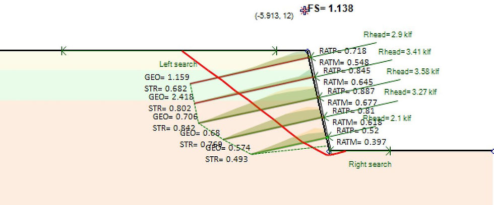
Slope stability analysis results in SnailPlus software

SnailPlus ist unsere Software zur Analyse der Hangstabilität und zum Entwurf von Bodennagelwänden. Obwohl Bodennagelung auch in unserem DeepEX-Softwareprogramm verfügbar ist, wurde SnailPlus entwickelt, um alle notwendigen Fähigkeiten in einem Paket zu vereinen.


Die Software folgt der FHWA-Methodologie für den Entwurf von Bodennagelwänden in einer interaktiven Umgebung, die auf dem Grundlayout von DeepEX basiert. Das bedeutet, dass Sie alle Zwischenbauzustände Ihrer Bodennagelwand einschließlich 3D-Lasten in einer interaktiven Umgebung einbeziehen können.


Zuletzt ist SnailPlus die einzige Software, die einen vollständig ausdruckbaren Bericht aller Entwurfsberechnungen erstellt.

Tunnel analysis in DeepEX

The procedure to create and analyze any quay wall type within the program is summarized in the following steps:

1. Create the Quay Wall model with the use of the powerful Model Wizard in minutes with all construction stages. 

2. Edit the Quay Wall structural section. 

3. Edit the soil properties and stratigraphy. 

4. Define the analysis assumptions, wave pressures and overtopping methods, and the seismic pressures method.

5. Review the results in graphs and tables on the model area for all construction stages and optimize the model.

SCHEDULE A FREE WEB DEMO

Intuitive interaktive Benutzeroberfläche

Grafische Modellierung

Vielseitigkeit bei Lasteingaben

Anpassung und Flexibilität

Umfassende Analyse

Detaillierte Berichterstattung

2

Vorteile

WARUM SNAILPLUS WÄHLEN?

Was gibt es Neues in SnailPlus 2024?

Export soil nail wall model sketches to DXF in SnailPlus

Exportieren Sie Skizzen des Bodennagelwandmodells nach DXF in SnailPlus Wir sind stolz darauf, bekannt zu geben, dass SnailPlus 2024 da ist! Die neueste Version unserer Software ist ein Beweis für unser Engagement für Innovation. Die verbesserte Schnittgenerierung für präzise Schichtkreuzungen, aktualisierte Betoncodes und verbesserte Berichtsausgaben unterstreichen unsere Hingabe, jeden Aspekt des Benutzererlebnisses zu verfeinern. Mit variablen Gesichtsdickenoptionen, der Einführung von vorgespannten Bodennägeln und aktualisierten Lastkombinationen gemäß AASHTO- und kanadischen Codes setzt SnailPlus 2024 einen neuen Standard für die Hangstabilitätsanalyse.
Verbesserungen und neue Funktionen von SnailPlus 2024:
 Verbesserte Schnittgenerierung für exakte Schichtkreuzungen
 Aktualisierte Betoncodes
 Aktualisierte Lastkombinationen gemäß AASHTO- und kanadischen Codes
 Verbesserte Assistentengenerierung
 Verbesserte Berichtsausgaben
 Variable Gesichtsdickenoptionen
 Vorgespannte Bodennägel
 Ausgabezeichnungen als DXF

3

Unsere Tutorials

WIE FUNKTIONIERT DIE SNAILPLUS-SOFTWARE?

4

Eigenschaften

HAUPTMERKMALE UND FÄHIGKEITEN VON SNAILPLUS

  • ÜBERLEGENE INTERAKTIVE BENUTZEROBERFLÄCHE
    SnailPlus ist eine äußerst benutzerfreundliche Software, die eine interaktive Modellbenutzeroberfläche bietet. In dem Modellbereich können wir alle Phasen erstellen und alle Projektparameter (externe Lasten, Bodennagelabschnitte, Spritzbetonabschnitte usw.) grafisch definieren. Alle Elemente im Modellbereich (Bohrung, Bodennägel, Verkleidung) können zugegriffen werden und ihre Eigenschaften können über benutzerfreundliche Dialogfelder definiert werden.
  • BERICHTE IN PDF UND MS WORD EXPORTIEREN
    BERICHTE IN PDF UND MS WORD EXPORTIEREN Die Berichte von SnailPlus können Tabellen und Diagramme mit allen untersuchten Modelleigenschaften und berechneten Ergebnissen enthalten. Wir können auch wählen, alle Strukturberechnungsgleichungen und das Berechnungsverfahren in den Bericht aufzunehmen. Die Berichte von SnailPlus können vorab angezeigt, im PDF-Format exportiert oder im Word-Format exportiert werden, damit sie vom Benutzer weiter bearbeitet werden können. Designabschnitte für den Bericht auswählen Bauabschnitte für den Bericht auswählen Berichtsdiagramme anpassen Berichtslayout definieren Berichtsabschnitte definieren Möglichkeit, Gleichungen und Berechnungen der Bauabschnitte im Bericht aufzunehmen Berichtsvorschau Berichte im PDF- und Word-Format exportieren
  • BODENEIGENSCHAFTEN - SPT-AUFZEICHNUNGEN - CPT-PROTOKOLLE
    Die Bodentypen, Bodeneigenschaften und Stratigraphien können in SnailPlus durch benutzerfreundliche Dialogfelder einfach definiert werden. In SnailPlus können wir eine unbegrenzte Liste von Böden erstellen und schnell alle Bodeneigenschaften definieren. Die Software bietet mehrere Schätzwerkzeuge (SPT-Schätzer und teilweise Schätzwerkzeuge für jede Eigenschaft mit wissenschaftlichen Methoden und Gleichungen). In SnailPlus können wir direkt SPT-Aufzeichnungen und CPT-Protokolle hinzufügen, die vom Software zur Schätzung verschiedener Bodeneigenschaften verwendet werden können. Liste der Bodentypen definieren Liste der Stratigraphien definieren (Bohrungen) Werkzeuge zur Schätzung der Bodeneigenschaften SPT-Aufzeichnungen CPT-Protokolle
  • Modell Wizard - Erstellen Sie ein Modell in Sekundenschnelle
    Der Modell Wizard von SnailPlus kann verwendet werden, um jede geneigte Oberfläche mit allen Bauphasen, Aushubarbeiten und der Installation von Bodennägeln und Verkleidungen in wenigen Minuten zu erstellen. Wir können die Registerkarten des Assistenten verwenden, um alle Projektparameter festzulegen (Parameter für die geneigte Oberfläche, Bodennägel - Kopfplatten und Schussbeton-Strukturabschnitte, Optionsstufen und Designstandards). Der Assistent erstellt das Modell automatisch und spart uns viel Zeit und Mühe bei der ersten Erstellung.
  • STRUKTURELLE UND GEOTECHNISCHE DESIGNKODES
    HelixPile hat viele internationale Designcodes und -standards für das Design und die Analyse (strukturell und geotechnisch) von Schraubpfählen implementiert. In HelixPile können wir ein Dienst- oder Faktordesign mit der Verwendung von US- und europäischen Standards durchführen. Wir können leicht zwischen mehreren US-, europäischen, australischen und chinesischen strukturellen Codes wählen. ACI 318-11 (Bewehrte Betonbauteile) ASD 1989 (Zulässige Spannungskonstruktion - Stahlbauteile) AASHTO LRFD 13. Ausgabe (Stahlbauteile) AISC 360 und 360-Zulässig (2010 und 2016) EUROCODE 2, 7 und 8 Spezifikationen AASHTO LRFD Lastkombinationen Europäische Codes (DIN, BS, XP94, DM, DA) Australische Standards (AS 3600, AS/NZS 4100) Chinesische Standards (CN)
  • PFAHLGRUPPEN - PFAHLFLÖSSE
    HelixPile kann sowohl Einzelschraubpfähle als auch Pfahlgruppen mit mehreren Pfählen entwerfen (das zusätzliche optionale Modul Pfahlgruppen ist erforderlich). Die Software kann auch Pfahlflöße entwerfen, wobei der kombinierte Effekt des Bodens unter dem Floß berücksichtigt wird (zusätzliches Modul zu unserer Pfahlgruppenoption). Einzelschraubpfähle Rechteckige Pfahlkappen Dreieckige Pfahlkappen Runde Pfahlkappen Sechseckige Pfahlkappen Achteckige Pfahlkappen Benutzerdefinierte Umfangspfahlkappen Pfahlflöße
  • PFAHLARTEN & HELIXKONFIGURATIONEN
    HelixPile kann sowohl vertikale als auch laterale Designs von Schraubpfählen durchführen. Die Schraubpfähle in HelixPile können jede typische Form haben (Rohre, quadratische Voll- und Hohlprofile). In jedem Pfahl können wir eine unbegrenzte Anzahl von Helixkonfigurationen definieren und zuweisen. Die Pfähle können vergroutet werden. Schließlich können wir eine externe Ummantelung am Pfahlkopf verwenden, um die laterale Kapazität des Pfahls zu erhöhen. Stahlrohre Quadratische Vollstahlprofile Quadratische Hohlstahlprofile Unbegrenzte Helixkonfigurationen pro Pfahl Vergroutete Pfähle Verwendung einer externen Stahlummantelung
  • AXIALE & LATERALE PFAHLANALYSE
    HelixPile kann sowohl vertikale als auch laterale Pfahlanalysen durchführen. HelixPile verwendet sowohl die Einzelplatten- als auch die Zylindermethode und berichtet über die kritischsten Ergebnisse. Die allgemeinen und die Helicap-Gleichungen können ausgewählt werden. Für das vertikale Pfahldesign können wir entweder die Vesic- oder die Meyerhoff-Hansen-Methode verwenden. HelixPile berechnet und prüft das Installationsdrehmoment des Schraubpfahls. Für die laterale Pfahlanalyse kann HelixPile entweder die definierte Last am Pfahlkopf verwenden und die entwickelten Moment-, Scher- und Pfahlverschiebungsdiagramme berechnen, oder es kann eine Pushover-Analyse durchführen, bei der die erforderliche seitliche Last berechnet und präsentiert wird, um eine spezifizierte Pfahlkopfverschiebung zu erreichen. HelixPile kann auch eine Setzungsanalyse durchführen. In der Software können wir eines der implementierten Pfahlakzeptanzkriterien auswählen oder unser eigenes definieren.
  • ÜBERLEGENE INTERAKTIVE BENUTZEROBERFLÄCHE
    HelixPile ist eine äußerst benutzerfreundliche Software, die eine interaktive Modellschnittstelle bietet. Im Modellbereich können wir verschiedene Belastungsstadien erstellen und alle Projektparameter (externe Lasten auf dem Pfahlkopf, Pfahlabteilungseigenschaften usw.) grafisch definieren. Alle Elemente im Modellbereich (Bohrung, Pfahl, externe Lasten) können zugegriffen und deren Eigenschaften durch benutzerfreundliche Dialoge definiert werden.
  • EXPORTIERTE BERICHT IN PDF & WORD
    HelixPile kann umfangreiche Berichte für alle geprüften Designabschnitte (Pfähle) und Belastungsstadien erstellen. Die Berichte in HelixPile sind vollständig anpassbar - der Endbenutzer kann immer alle Berichtsabschnitte auswählen, die im endgültigen Bericht enthalten sein sollen. Die Berichte von HelixPile können Tabellen und Grafiken mit allen geprüften Modelleigenschaften und berechneten Ergebnissen enthalten. Wir können auch wählen, alle strukturellen Designgleichungen und Berechnungsverfahren in den Bericht aufzunehmen. Die HelixPile-Berichte können vorschauend betrachtet, als PDF oder im Word-Format exportiert werden, sodass sie vom Benutzer weiter bearbeitet werden können. Wählen Sie die zu berichtenden Designabschnitte aus Wählen Sie die zu berichtenden Bauphasen aus Passen Sie die Berichtsgrafiken an Definieren Sie das Layout des Berichts Definieren Sie die Berichtsabschnitte Möglichkeit, Gleichungen und Berechnungen der Phasen zu berichten Berichtsvorschau Berichte in PDF- und Word-Formaten exportieren
  • AUTO-MODELLGENERIERUNG UND -OPTIMIERUNG
    Der Modell-Assistent von HelixPile kann verwendet werden, um jedes Tiefgründungsmodell in Minuten zu erstellen. Wir können die Registerkarten des Assistenten verwenden, um alle Projektparameter (Analyseeinstellungen, Pfahltyp und strukturelle Abschnitt, externe Lasten und Designstandards) zu definieren. Der Assistent erstellt das Modell automatisch, was uns viel Zeit und Mühe für die anfängliche Erstellung erspart. HelixPile verfügt über ein automatisches Längenoptimierungswerkzeug. Die Software kann einen definierten Schritt verwenden, um die Pfahltiefe bis zu einer definierten Tiefengrenze zu erhöhen, wobei die axiale Zug- und Druckkapazität in jedem Schritt berechnet wird.
  • BODENEIGENSCHAFTEN - SPT-AUFZEICHNUNGEN - CPT-PROTOKOLLE
    Die Bodentypen, Bodeneigenschaften und Stratigraphien können in HelixPile einfach über benutzerfreundliche Dialoge definiert werden. In HelixPile können wir eine unbegrenzte Liste von Böden erstellen und schnell alle Bodeneigenschaften definieren. Die Software bietet mehrere Schätzungswerkzeuge (SPT-Schätzer und teilweise Schätzungswerkzeuge für jede Eigenschaft mit wissenschaftlichen Methoden und Gleichungen). In HelixPile können wir direkt SPT-Aufzeichnungen und CPT-Protokolle hinzufügen, die von der Software verwendet werden können, um verschiedene Bodeneigenschaften zu schätzen. Liste der Bodentypen definieren Liste der Stratigraphien (Bohrungen) definieren Schätzungswerkzeuge für Bodeneigenschaften SPT-Aufzeichnungen CPT-Protokolle
  • MEHRERE WANDTYPEN
    Die QuayWalls-Software kann jede Art von Schwerkraftquerschnittswand entwerfen, indem sie Boden-, Wasser-, Wellen- und seismische Drücke auf das Wandsystem berechnet. QuayWalls kann für Entwurf und Analyse von: Kragwände Segmentwände Boxkaissonwände mit Bodenfüllzonen T-förmige Wände Benutzerdefinierte Wände
  • WELLENDRUCK & ÜBERSTRÖMUNG
    QuayWalls kann Wellendruck mit einer Reihe von etablierten Methoden berechnen. Die anfänglichen Wellenhöhen und Wellenlängen können mit implementierten Empfehlungen geschätzt oder manuell durch den Benutzer über ein benutzerfreundliches Dialogfeld definiert werden. Schließlich kann QuayWalls automatisch Überströmungsraten schätzen, da es Berechnungen des durchschnittlichen Überströmungsvolumens unter Verwendung der PROVERBS-Gleichungen durchführen kann. Goda SainFlou Küsteningenieurhandbuch 2011 Allsop PROVERBS
  • STABILITÄTSANALYSE VON BÖSCHUNGEN & NAGELWANDKONSTRUKTION
    SnailPlus ermöglicht die globale Stabilitätsanalyse von Böschungsoberflächen (einfach oder mit Bodennägeln verstärkt). SnailPlus kann die kritischste Böschungsoberfläche berechnen und den Sicherheitsfaktor für die Böschungsstabilität unter Verwendung mehrerer wissenschaftlicher Methoden ermitteln. Bodennägel können in Böschungsoberflächen verwendet werden. SnailPlus berechnet die Auswirkungen der Bodennägel auf die Stabilitätsanalyse der Böschung. Bishop-Methode Morgenstern-Price-Methode (Allgemeines Grenzgleichgewicht) Spencer-Methode Französische Clouterre-Normen für die Bodennagelkonstruktion
  • VOLLSTÄNDIGES DESIGN DER SHOTCRETE-VERKLEIDUNG
    SnailPlus kann die Shotcrete-Verkleidung entwerfen. Verkleidungen in zwei Stufen (temporär und permanent) können ebenfalls definiert und mit der Software analysiert werden. SnailPlus führt Überprüfungen an den Kopfplatten der Bodennägel durch. Design der Shotcrete-Verkleidung Zweistufige Verkleidung verfügbar Überprüfungen der Kopfplatten
  • DESIGNNORMEN UND SPEZIFIKATIONEN
    SnailPlus hat verschiedene Standards und Spezifikationen für das Design von Bodennägeln und Shotcrete-Verkleidungen implementiert. In SnailPlus können wir ACI- und FHWA-Spezifikationen für das strukturelle Design auswählen. In der Software können wir Methoden des Grenzzustandes der Gebrauchstauglichkeit oder des Grenzzustandes der Tragfähigkeit verwenden. ACI Direktmethode FHWA- und FHWA-LRFD-Methoden LRFD WSDOT 2019 (GDM) ASD-Sicherheitsfaktoren LRFD FHWA GEC-7 EUROCODE 7 - ULS-Ansatz
  • SUCHOPTIONEN FÜR MEHRERE BÖSCHUNGSOBERFLÄCHEN
    SnailPlus kann die kritischste Böschungsoberfläche unter Verwendung verschiedener Suchmethoden für Böschungsoberflächen lokalisieren und berichten: Kreisförmige Böschungsoberflächen Kreisförmige Oberflächen mit aktiven und/oder passiven Keilen Automatische Suchmethode für Oberflächen Trilineare Suchmethoden für Oberflächen Oberflächen mit Blocktyp-Versagen Benutzerdefinierte Böschungsoberflächen
  • What is the difference between DeepFND and HelixPile?
    DeepFND and HelixPile are two similar, powerful software programs for the design and evaluation pile foundations. The programs can perform structural and geotechnical, lateral, and axial analysis of any foundation pile (single piles, pile groups and pile rafts).The only difference between the two programs is the available pile types. DeepFND can design all pile sections and pile types (helical and non-helical – drilled, driven, caissons, micropiles, CFA piles and more), whereas HelixPile can design only helical piles.
  • Does your program check the structural capacities of the piles as well?
    DeepFND and HelixPile software have implemented several structural codes used worldwide. The software do all calculations according to the selected standard and calculate the pile moment and shear capacities. All structural design checks and equations can be included in the software reports. Figure: Pile Moment, Shear and Displacement Diagrams - DeepFND
  • Can your software design pile caps with a group of piles?
    Our foundation pile design software can design single foundation piles, pile groups and pile rafts. The following pile cap shapes are available: Rectangular Pile Caps Triangular Pile Caps Circular Pile Caps Hexagonal Pile Caps Octagonal Pile Caps User-Defined Perimeter Pile Caps Pile Rafts The user can create a concrete cap of any shape and define the pile configuration (pile locations and structural sections). The program can calculate the load that is transfered on each pile, considering the pile location and analyze all piles. Figure: A Rectangular Cap with Concrete Piles - DeepFND Figure: A Circular Cap with Helical Piles - DeepFND and HelixPile
  • What type of Pile Analysis can your software do?
    Our foundation piles design software DeepFND and HelixPile can perform axial and lateral analysis of any pile type. The programs can calculate the pile shaft resistance and the bearing capacity of the piles, taking into consideration the pile installation method. In addition, the software can do lateral pile analysis, calculating the pile displacements, moment and shear diagrams for any applied load combination on the pile head.
  • How is the pile cap modelled, rigid or finite stiffness?
    The pile cap is modelled with quadrilateral shell finite elements. The user can post process stress resultants and displacement of the cap.
  • What type of loads can i add on a single pile?
    In DeepFND and HelixPile software, we can add axial loads, lateral loads and external moments on both directions on each single pile head. In addition, we can add a distrubuted lateral load along the pile (user-defined elevations and magnitude). The following list summarizes the loads that can be applied on each axis. - Axial Loads (Z Axis) In DeepFND and HelixPile we can add axial loads on the pile head. A positive axial load magnitude is a compression load (downwards) and a negative magnitude is a tension load (uplift). - Lateral Loads (X Axis) The X-Axis is along the screen. A positive magnitude is a left-to-right load, and a negative magnitude is a right-to-left load. - Lateral Loads (Y Axis) The Y-Axis is on the perpendicular direction of the screen. A positive magnitude is an inwards load, and a negative magnitude is an outwards load (from the screen to the user). - External Moments (X and Y Axis) The external moments on each direction can be defined for each stage. A positive moment magnitude is a counter-clockwise moment, a negative value is a closkwize moment.
  • Which structural section types can i use in DeepFND?
    DeepFND software is designed to handle a wide variety of pile types, making it versatile and efficient for deep foundation design and analysis. Within minutes, the software can perform both axial and lateral pile analysis, as well as structural design for different types of piles. Whether you're working with traditional or more specialized pile systems, DeepFND offers robust design capabilities. One of DeepFND’s key features is its ability to recognize the material type of the pile and automatically apply the relevant structural code. These include major standards such as the International Building Code (IBC), AASHTO, ACI, Eurocode 2, Eurocode 3, NTC, AISC, Canadian standards, Australian codes, Chinese codes, and many more. This ensures that the software computes structural capacities accurately and performs all required structural checks in compliance with the selected code. Pile Types Available in DeepFND DeepFND provides users with a comprehensive range of pile types and configurations. These can be quickly defined using the model wizard, where you can specify wall section properties such as dimensions, reinforcement, and material characteristics. Below are the main pile types that DeepFND supports: 1. Helical Piles Supported shapes: Pipes, square solid, and square hollow sections. In DeepFND, helical piles can be customized with an unlimited number of helix configurations to meet your project requirements. Additional options: You can choose to grout the piles for improved capacity and apply external casing to the pile head to further enhance its lateral capacity. 2. Non-Helical Piles Types: DeepFND supports a variety of common piles, including drilled shafts, driven piles, CFA piles, caissons, and more. Shapes: These piles can be modeled in different geometric forms such as circular, square, hollow, and octagonal sections. Materials: You can simulate piles made from reinforced concrete, structural steel, or timber (wood). Special configurations: Non-helical piles can also be designed as belled piles for increased bearing capacity at the base. In addition, DeepFND allows for composite pile sections where the shape or material of the pile can change along its depth. For timber piles, the software can generate tapered sections to account for naturally varying dimensions. 3. Stone Columns Stone columns are another type of foundation that DeepFND can simulate, including configurations with mechanically stabilized earth (MSE) grids such as geotextiles and geogrids to reinforce the structure. Full List of Supported Pile Types: Helical piles (pipes, square solid, or square hollow sections) Reinforced concrete piles (circular or square sections) Prestressed concrete piles, including those with GFRP (Glass Fiber Reinforced Polymer) or CFRP (Carbon Fiber Reinforced Polymer) reinforcements Steel piles (H-piles, pipes, channel sections) Belled type piles Timber piles (tapered or straight wood piles) Steel core piles Composite piles (with varying sections along the depth) Stone columns with MSE grid reinforcement DeepFND’s comprehensive suite of supported pile types and configurations ensures that it can meet the demands of any deep foundation project, providing the flexibility and precision needed for modern engineering designs. Whether you're designing simple or complex foundations, the software is equipped to handle your project with ease.
  • Can i check a certain pile under different load combinations?
    In DeepFND and HelixPile software, the user can add construction stages in any foundation pile section model. The stages in our foundation pile design programs work as loading stages, we can access and define tha axial tension and compression loads, as well as, the lateral loads and external moments for different stages and the software will calculate the pile capacities for all load combinations. Figure: Pile Loading in different stages
  • How can i add a CPT log in your software?
    The user can create the file in excel and then export it as tab delimited. The file can be of .txt or .cor format. The files should follow a specific format - 1st row should be parameter names, second row should be the units, and then row by row (without the first column numbering), we need to include four specific columns as presented in the image below: After the cpt log import, the user needs to press on the "Process Data" button, so the rest of the properties are estimated:
  • Is it possible to view the Moment and shear and interaction diagrams used to calculate reinforcement?
    In DeepFND we can view the interaction diagrams for each concrete section. We can also view Moment and shear along the pile, with the capacity indicated with the red lines left and right of the M and Q diagrams. All diagrams, including the interaction diagrams can be included in the exported reports.
  • For a piled raft, how is the influence of the raft on the soil taken into account?
    When the raft option is enabled the soil beneath the cap is considered through a non-linear Winkler base (either elastoplastic or exponential plastic formulation based on user selection). Influence of the raft on the soil is taken into account through the automatic configuration of the free length of the internal piles based on the intersection between the pile influence regions. The soil enclosed within the free length region is considered to be moving along with the cap and piles , thus shear resistance contribution along the perimeter of the piles within the free length region is considered to be zero.
  • Can i create and save my own piles with helix configurations in DeepFND & HelixPile?
    DeepFND and HelixPile software programs can design any common helical pile shape (pipes, square solid and square hollow sections). We can easily select the section shape and define the section parameters (dimensions, material properties etc). On each created pile section, we can fast generate several helix configurations, by defining the number of helixes, the helix plate diameter and thickness, and the plate spacing. All the generated helix configurations can be saved on a partial database, unique for each generated pile. Later, we can simply access and assign one of the generated helix configurations to the pile. We can select to use an external casing on any helical pile, in order to increase the lateral pile capacity. We simply need to define the casing section and the length from the pile top, where the casing is placed. The generated helical pile sections can be saved in a folder in any local device, and they can be loaded in any software file. Finally, any pile in DeepFND and HelixPile can be grouted. For grouted piles, we need to define the grout diameter, and the part of the pile which is grouted.
  • What type of loads can i add on a pile cap?
    In DeepFND and in HelixPile, we can define several loads on a pile cap, as follows: A. Single load at the pile cap centroid This is the default option in the software Wizard. The user can automatically define the maximum axial load on the cap, the maximum lateral loads and external moments on each direction (X and Y axis), as well as the torsional moment that can be applied on the cap. B. Point Loads on User-Defined Locations This option allows the user to create load groups of point loads and define the load coordinates, as well as the magnitude of the axial load, and the lateral load and moment at every axis (X and Y). C. Area Loads on the Pile Cap This option allows the user to assign an area pressure load on the whole cap surface, or at user-defined locations. D. Linear Loads on the Pile Cap This option allows the user to assign linear loads between 2 user-defined points on the pile cap.
  • What in the Max Stress Check result i get in the summary table after the analysis?
    The maximum stress check result is the most critical of all structural and geotechnical checks. DeepFND calculates all and reports there the most critical one (biggest). In general, all checks in the program are (applied force/Capacity). So, Max Stress Check is the most critical of: 1. (Maximum Compression Load) / (Compression Capacity) (Geotechnical check) 2. (Maximum Tension Load) / (Tension Capacity) (Geotechnical check) 3. (Maximum plate reaction) / (Plate Ultimate Capacity) (Structural Check) 4. (Maximum Pile Moment) / (Pile Moment Capacity) (Structural Check)
  • How is the structural resistance determined?
    The structural capacity is calculated in accordance to the standards selected by the user and the nature of the section (concrete, steel, timber, composite etc). The user can define the structural section (concrete piles with internal reinforcing cage, steel casing, drivel steel beams with or without concrete covers, timber piles and then the software uses the corresponding design codes.
  • What theory is used for the lateral pile load analysis?
    The software uses P-Y curves to simulate the soil, while an Euler-Bernoulli beam (elastic or inelastic pile behaviour with distributed plasticity along the pile) is used for the pile. A full FEM analysis engine is currently under development and will be implemented in the DeepFND/HelixPile 2021 versions.
  • How does DeepFND consider the pile cap side lateral response (if the cap is inside the soil)?
    For the lateral resistance contribution of the cap there are 2 mechanisms that need to be included, (a) the passive resis